
Injection mold maintenance is often discussed as if it were a simple weekly or annual checklist. In practice, the right schedule depends on shot count, resin and additives, mold construction, cooling-water condition, cycle severity, cosmetic requirements, storage conditions and the cost of an unexpected stoppage. A useful plan therefore combines time-based tasks with usage-based checks and condition-triggered repair. It should also say who performs the work, what evidence is retained and when a tool is released back to production.
For a buyer, the objective is not to prescribe one universal interval. It is to make the supplier’s assumptions visible and protect the part, the tool and the production schedule. Ask for the tool’s maintenance history, a documented reaction plan and a clear distinction between cleaning, adjustment, repair, modification and replacement. The supplier’s [process](/process), [quality](/quality) and [request a quote](/request-a-quote) discussions should all use the same revision-controlled information.
A maintenance interval is a starting hypothesis, not proof that a mold is healthy. Release a tool by recorded condition and part evidence, then adjust the interval when usage, resin, defects or inspection data show that the risk has changed.
01
1. Separate preventive maintenance from repair and modification
Preventive maintenance is planned work intended to preserve the mold’s known condition. It can include cleaning the cavity and core, clearing vents, checking cooling circuits, inspecting guide and ejector components, lubricating approved moving interfaces and protecting the tool for storage. The work should be defined against the actual tool and material rather than copied from a generic press-maintenance sheet. Industry checklists commonly treat cavity condition, vents, cooling, ejection and records as connected maintenance topics.[1]
Repair starts when a condition has already changed or a failure is suspected. Examples include correcting flash at a shutoff, replacing a damaged ejector pin, restoring a worn slide, repairing a leaking water circuit or reworking a vent after repeated burn marks. A design modification is different again: moving a gate, changing a parting line or altering a cooling channel may affect the approved product and should pass through engineering change control. Keep these categories separate in the purchase order, quotation and maintenance log so a recurring service is not used to hide a tool change.

02
2. Build intervals from usage, material and risk
A calendar can help assign ownership, but shot count and condition usually provide a better trigger for many tasks. A high-cavitation production mold may accumulate wear faster than a low-volume prototype tool. Glass-filled or mineral-filled compounds can be more abrasive than an unfilled resin, while corrosive or moisture-sensitive materials can create different cleaning and preservation needs. Hot-runner components, unscrewing mechanisms, slides, lifters and tight shutoffs can also need separate inspection logic.
Start with an interval matrix that states the trigger, task, acceptance check, responsible party and escalation path. Then review it after the first production runs. Do not assume that a supplier’s standard interval transfers unchanged between tools. Published maintenance guidance also cautions that a preventive programme is not one-size-fits-all and should reflect the tool, production conditions and observed risk.[2]
| Trigger or cadence | Typical focus | Evidence before release | Escalate when |
|---|---|---|---|
| Every run or shift handover | Record shots, alarms, visible leakage, abnormal noise, flash, short shots or cosmetic change; confirm the tool is left clean enough for the next run. | Run log, operator observation and retained defect sample or image where relevant. | A repeatable defect, leak, sticking action or unexplained process adjustment appears. |
| Between planned production campaigns | Clean cavity and core surfaces, inspect vents and parting surfaces, check ejection and slides, and confirm water connections and plugs. | Maintenance entry with findings, parts replaced and photos or measurements for critical conditions. | Damage, wear, corrosion, blocked vents or a cooling-flow concern exceeds the agreed limit. |
| Usage-based review | Inspect wear components, guide systems, shutoffs, inserts, hot-runner interfaces and cavity condition at a defined shot-count or cycle-count trigger. | Shot count, inspection checklist, dimensional or functional sample evidence and open actions. | Wear threatens flash, burrs, alignment, release, appearance or a critical dimension. |
| Periodic engineering review | Review defect trends, cycle changes, repairs, downtime, spare parts, water quality and whether the interval remains suitable. | Trend summary, corrective-action status and revised maintenance plan if needed. | The same issue returns, the process window narrows or the tool no longer supports the approved requirement. |
| Before long-term storage or transfer | Clean, dry, preserve, protect moving parts and document connectors, loose components, plugs, lifting points and storage conditions. | Condition report, preservation record, inventory and photographs of interfaces. | Corrosion, missing components, trapped moisture or uncertain ownership of open work is found. |
03
3. Inspect the failure-prone systems, not only the cavity face
The molded surface is visible, but many maintenance problems begin elsewhere. Vents can become restricted and contribute to gas-related marks or incomplete filling. Cooling passages can accumulate scale or contamination, reducing heat-transfer consistency and increasing cycle variation; the correct test method and acceptance limit should be agreed with the tool and process team rather than inferred from a visual check. Water leaks, blocked circuits and damaged plugs also create production and corrosion risk.
Ejection and guidance require the same discipline. Inspect ejector pins, return mechanisms, plates, guide pins, bushes, slides, lifters, locks and springs for wear, scoring, looseness or abnormal resistance. Use only lubricants compatible with the tool, resin and process requirements, and record where they were applied. For hot-runner or unscrewing systems, define supplier-specific checks and do not treat a cold-runner inspection list as complete. A maintenance supplier should identify what can be checked in production and what requires a tool-room inspection.
04
4. Make repair decisions from defect evidence
A defect is a signal, not an automatic instruction to polish or weld the mold. Flash may point to shutoff wear, mismatch, excessive clamp force, process conditions or contamination. Burn marks may involve venting, filling or process settings. Drag marks may involve draft, texture, release direction, lubrication or damaged steel. A dimensional shift may be related to cooling, process drift, material or measurement—not only cavity wear. Diagnose the mechanism before authorising a repair that changes geometry.
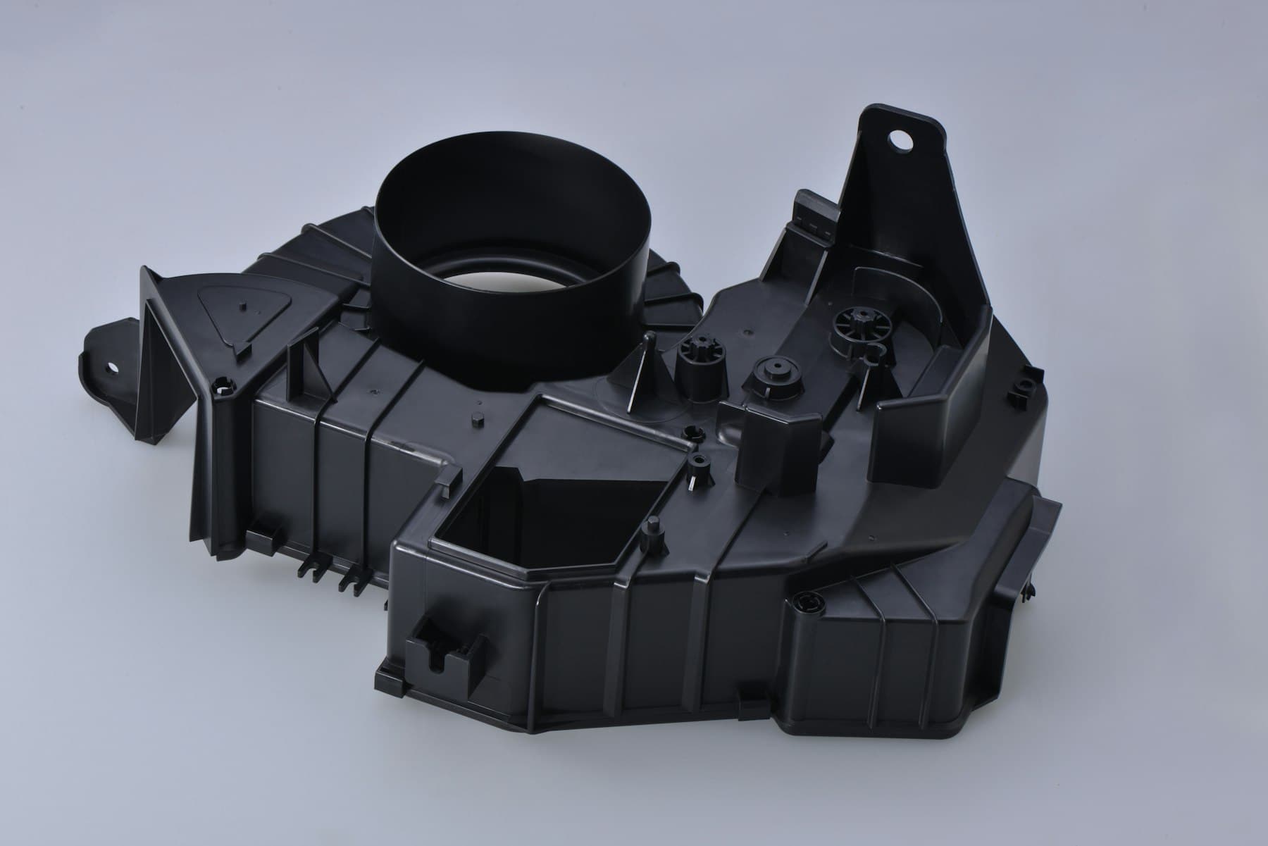
Ask the supplier to link the symptom to the suspected location, containment action, proposed correction and verification method. The repair record should identify the tool revision, cavity or insert, date, shot count, person or team, material and process context, before-and-after condition, parts removed, measurements and approval. If steel is added, a shutoff is reworked or a critical surface is altered, request updated inspection or first-off evidence. The product team should decide whether the repair is a like-for-like restoration or an engineering change.
05
5. Define a buyer-ready maintenance record and release gate
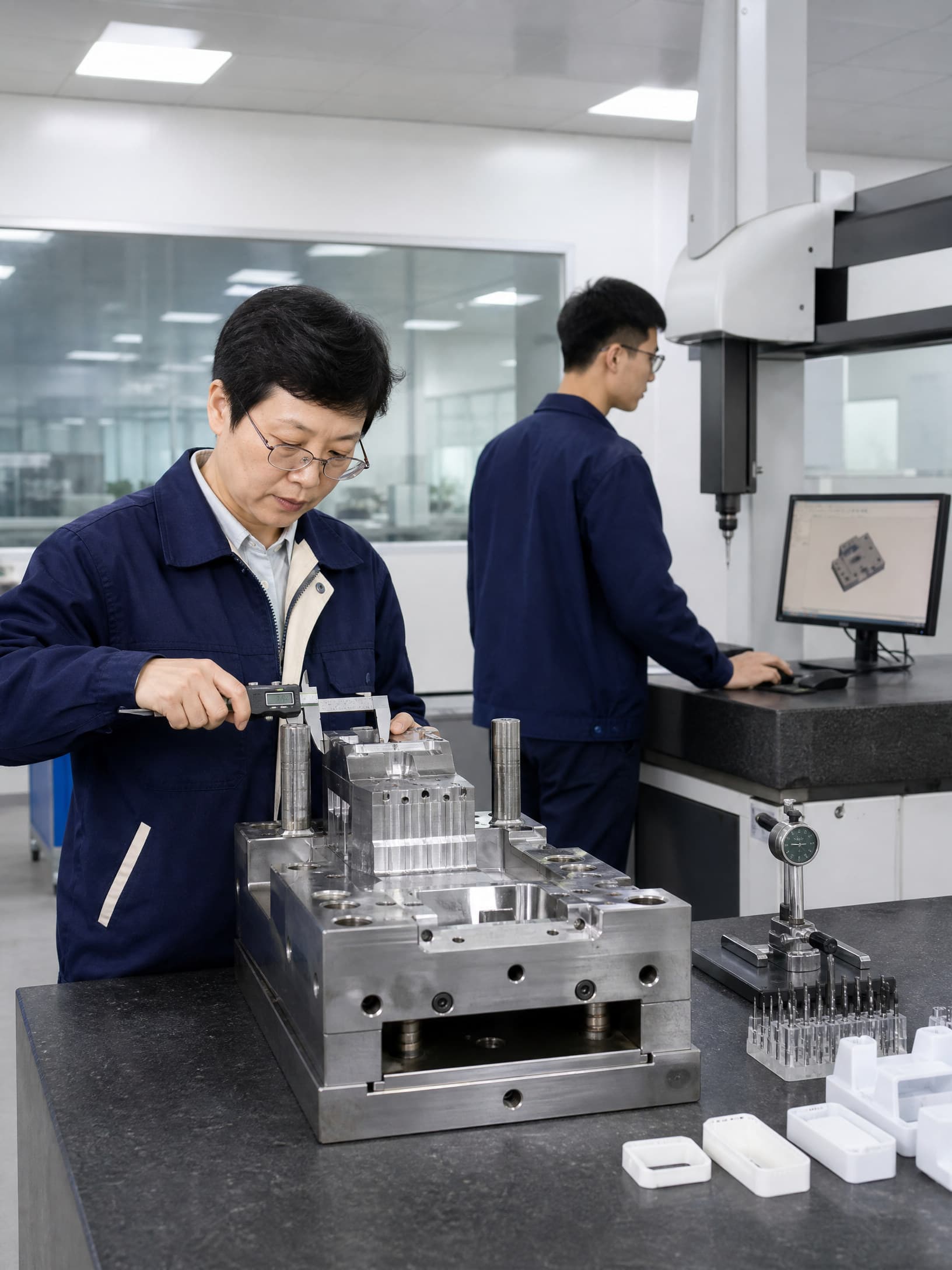
A maintenance plan has value only when another team can understand what happened and what remains open. At minimum, the record should identify the mold, part and revision; cavity count; shot or cycle count; resin and grade; production date; maintenance trigger; work performed; findings; replaced or repaired components; lubrication or preservation materials; photographs or measurements; responsible person; next due trigger; and release decision. For a transferred or customer-owned tool, keep the record with the tooling handover package rather than in an unshared local spreadsheet.
Set a release gate that matches the consequence of failure. A cosmetic consumer part may need appearance samples and cavity checks; a sealing or safety-related interface may need dimensional, assembly or functional evidence. If a repair could affect fit, form or function, approve representative parts made after the repair and compare them with the controlled requirement. Do not accept a maintenance tick-box as evidence that the tool is ready when a defect trend or open deviation remains. A supplier’s [capabilities](/capabilities) and [FAQ](/faq) pages can start the conversation, but the programme-specific maintenance plan belongs in the quotation, quality agreement or tooling handover.
06
6. Compare suppliers on maintenance transparency, not promises
When comparing tooling or molding suppliers, ask each bidder to state what routine maintenance is included, what is chargeable repair, how emergency work is prioritised, which spare parts are recommended and how the buyer receives records. Ask whether shot counts are captured by cavity, tool or programme, and how a tool is handled when it moves between machines or sites. Clarify who authorises a geometry change and who pays for a repair caused by normal wear, misuse, an undocumented process change or an agreed design decision.
A credible response does not need to promise a fixed tool life or zero downtime. It should show the inspection points, assumptions, reaction times, evidence format and limitations. Include the maintenance discussion in the same RFQ review as lead time, quality documentation, sample approval and ownership. The most useful next step is to send the model, drawing, resin direction, volume profile, known defects and existing tool history through InjeForm’s [request-a-quote](/request-a-quote) route so the schedule can be scoped against the actual programme.
Practical takeaway
Before you move
to the next review.
- The plan distinguishes routine cleaning and inspection from repair, modification and replacement.
- Intervals use visible triggers such as shots, cycles, campaigns, storage and defect conditions—not a calendar alone.
- Cavity, vents, parting surfaces, cooling circuits, ejection, guidance, slides, hot-runner or unscrewing systems are assigned clear checks.
- The supplier records tool ID, part revision, resin, shot count, findings, work performed, components changed, measurements and next due trigger.
- A repeat defect has a containment, root-cause hypothesis, repair decision and verification plan before production release.
- The quotation or quality agreement states maintenance ownership, chargeable repair, change approval, spare parts, records and emergency response expectations.
FAQ
Common questions
How often should an injection mold receive preventive maintenance?
There is no safe universal interval. Use the tool’s shot count, resin and additive package, cycle severity, cooling and storage conditions, critical features, defect history and supplier inspection findings to set an initial schedule. Review the interval after production evidence rather than treating a weekly, monthly or annual label as proof of condition.
What is the difference between injection mold repair and preventive maintenance?
Preventive maintenance is planned work intended to preserve an acceptable condition, such as cleaning, vent inspection, lubrication of approved interfaces and checks of cooling or ejection. Repair restores a changed or failed condition, such as a worn shutoff, damaged ejector or leaking circuit. A geometry change is an engineering modification and should be separately reviewed and approved.
Should mold maintenance be based on hours or shot count?
Use the trigger that best represents the risk, and often record both. Shot count reflects repeated mechanical and thermal cycles, while elapsed time matters for corrosion, storage, moisture and some maintenance materials. For multi-cavity or high-wear tools, combine the count with condition checks and defect trends.
What records should a buyer request after mold repair?
Request the tool and part revision, cavity or insert location, date, shot count, resin and process context, observed problem, containment, work performed, parts changed, measurements or photographs, responsible person, deviations, verification samples and release decision. If the repair can affect fit, appearance or function, request updated inspection or functional evidence.
When should a mold be repaired instead of replaced?
Compare the failure mechanism, remaining tool condition, repairability, required geometry, production risk, spare-part availability, downtime and cost. A repair may be sensible when the affected area is identifiable and verification is practical. Replacement or a new insert may be safer when wear is widespread, the steel or mechanism is no longer stable, or repeated repairs cannot demonstrate the approved requirement.
References
Source material
- [1] Xometry, “Injection Mold Maintenance Checklist.”
- [2] Kaysun Corporation, “Extend Injection Mold Tool Life with Preventative Maintenance.”
- [3] Plasticstoday, “Mold Maintenance: The Key to Peak Performance.”
- [4] Plastics Technology, “Back to Basics on Mold Venting.”
This guide is general information for early procurement and engineering discussion. It does not replace product-specific DFM, qualification, validation, regulatory assessment or legal advice.