
An agricultural equipment cover is rarely just a cosmetic shell. It may shield belts, electronics, hydraulic or control components; provide access through hinges or latches; carry fasteners and guards; and maintain alignment while exposed to sunlight, water, dust, fertilizers, crop-treatment chemicals and repeated cleaning. A quote based only on an outer STEP file can miss the load path, drainage, chemical exposure, UV ageing, warpage and inspection work that determine whether a part survives field use.
Source the molding program as a controlled package: released CAD and drawings, mating interfaces, field exposure matrix, exact material direction, structural features, tool assumptions, sample gates and traceable inspection evidence. InjeForm’s [request-a-quote](/request-a-quote) route is most useful when the RFQ explains what the cover protects, how it is mounted and what must remain functional after exposure.
Buying rule: quote the cover’s environment and load path, not only its projected area and resin family. UV, chemicals, vibration, fasteners and service access should be visible assumptions before tooling is approved.
01
1. Build the RFQ around the machine, not an isolated cover
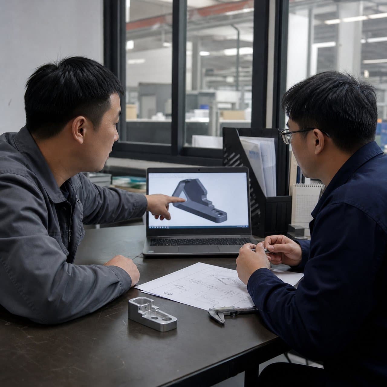
Identify the application precisely: tractor side cover, sprayer shroud, planter guard, harvest-equipment access panel, sensor cover, battery enclosure or another part. Provide the controlled 3D model, 2D drawing, revision, mating frame, hinges, latches, fasteners, gaskets, inserts, adjacent hoses or wiring and the removal path. Mark mounting holes, datum surfaces, seal lands, access openings, operator touch points, no-drill zones and areas that must remain clear for airflow or heat dissipation.
Translate the field environment into inputs. State geographic exposure or UV intent, seasonal temperature range, rain and standing-water conditions, dust or mud, washdown pressure if known, fertilizer or pesticide contact, hydraulic oil or fuel proximity, cleaning agents, vibration, impact from stones or crop material and expected service life. Name the consequence of failure: loose cover, water ingress, exposed moving parts, blocked airflow, lost sensor alignment or an unsafe access condition. The [industrial equipment application page](/products/industrial-equipment) can frame the discussion, but the machine maker’s requirements govern.
Add program and logistics assumptions: annual demand, seasonal ramp, spare-part forecast, cavity expectation, color and texture, packaging orientation, regrind policy, destination and whether the mold may be transferred. Ask bidders to itemize gate, parting line, slides or lifters, inserts, secondary operations, machine fit, inspection and testing assumptions so a low unit price does not conceal an incomplete scope.
| RFQ input | Evidence or file to provide | Risk addressed |
|---|---|---|
| Machine interface | Frame, hinge, latch, fastener, gasket and mating-part CAD or controlled dimensions | Misalignment, poor sealing, rattle or difficult service removal |
| Field exposure | Chemical list, UV/weather intent, temperature, washdown and vibration conditions | Material or geometry chosen without the actual duty cycle |
| Load path | Mounting loads, guard function, impact direction and unsupported-span information | Cracked bosses, loose fasteners or cover deflection |
| Acceptance basis | CTQs, datums, visual boundaries, fit checks and required records | Disagreement about what a production-ready cover means |
02
2. Review cover geometry as a structural and service system
Start with the load path from the cover skin into ribs, bosses, perimeter flanges, hinges, latches and the machine frame. A broad panel may need curvature, beads, ribs or gussets to resist oil-canning and vibration, but each thickened feature can create sink, differential shrinkage or a difficult cooling condition. Use coring and gradual transitions where practical, then confirm the proposed geometry with the product engineer and the [DFM and mold-design](/injection-mold-design-dfm) review before steel is cut.
Treat fastener bosses and hinge towers as engineered interfaces. Specify screw type, torque, insert or self-tapping intent, repeated service cycles, pull-out or stripping concern, clamp load and allowable distortion. Check boss support, rib intersection, draft, tool access and clearance for the driver. A supplier can recommend moldable geometry and insert loading, but the equipment owner should set the structural and service acceptance criteria.
Plan for field handling. Add draft and radii around hand access, protect latches from accidental release, provide drainage rather than trapping water, and keep ejector marks, weld lines and gate vestiges away from sealing or operator-contact zones where possible. Review cover deflection against fan clearance, belt or shaft movement, hot surfaces and sensor line-of-sight. If a guard function is safety-relevant, the responsible machinery designer must define the applicable risk assessment and validation; molding evidence alone is not a safety approval.
| Feature | Design risk to review | Supplier evidence to request |
|---|---|---|
| Large cover skin | Oil-canning, warpage, vibration noise or inadequate impact margin | Sectioned DFM, gate/cooling concept, flatness and fit plan |
| Bosses and ribs | Sink, knit lines, cracking around screws or uneven load transfer | Cored geometry review, insert/fastener assumptions and sample torque checks |
| Hinge and latch | Stress concentration, wear, accidental release or difficult service access | Assembly sequence, cycle expectation, retention check and tool-action review |
| Perimeter flange and seal | Leak path, flash, compression variation or trapped water | Mating drawing, seal stack, datum scheme and functional fit evidence |
03
3. Choose resin against chemicals, UV and mechanical duty
Screen materials against the exact exposure rather than approving a family name. PP may be a practical direction for some lightweight, chemical-exposed covers; PA or PA-GF may suit stiffness and structural features where moisture conditioning, fiber orientation and chemical compatibility are understood; PBT can be relevant around stable equipment or electrical-adjacent interfaces. These are starting directions only. The exact grade, reinforcement, stabilizer package, colorant, shrinkage data and processing window must be matched to the part and the machine environment.
For chemical exposure, list the formulation, concentration, temperature, contact time, frequency, wiping or immersion method and whether the part is stressed during contact. Fertilizer concentrates, pesticides, oils, fuels, detergents and hard-water residues can behave differently, and compatibility can change with molded-in stress, weld lines, colorants and temperature. Request resin-maker data and agree representative testing on stressed features; do not treat a general “chemical resistant” label as a qualification.
For UV and weathering, specify whether the cover is shaded, intermittently exposed or continuously outdoors, along with color retention, chalking, embrittlement, gloss or mechanical-retention expectations. ISO 4892-2 describes laboratory exposure methods for plastics, but the applicable cycle, duration and pass criteria remain product-specific. A UV-stabilized grade or black color may be a useful design direction, yet neither automatically proves field life. Include any required conditioning, impact, fastener-retention and dimensional checks in the release plan.
| Decision factor | Buyer question | Evidence before release |
|---|---|---|
| Chemical contact | Which named chemicals, concentrations, temperatures and contact durations occur? | Exact grade and additive identity, resin documentation and agreed compatibility test |
| UV/weather | What exposure, appearance change and retained function are acceptable? | Stabilizer/color basis, defined exposure method and post-exposure functional review |
| Structural duty | What stiffness, impact, vibration and fastener loads apply? | Material data plus part-level deflection, impact, torque or retention evidence |
| Moisture and temperature | Does conditioning change dimensions, clips, seals or bosses? | Conditioning state, dimensional inspection and assembled fit check |

04
4. Make inspection prove the cover works on the machine
Build the inspection plan around interfaces and failure modes. Identify datums for frame fit, hinge position, latch engagement, seal compression, mounting-hole location, sensor alignment and clearance to moving or hot equipment. Add CTQs for warpage, flatness, flange profile, boss position, wall or rib features where structurally relevant, and appearance boundaries for visible surfaces. ISO 20457 can inform molded-part tolerancing discussions, but the released drawing and functional requirements remain the acceptance basis.
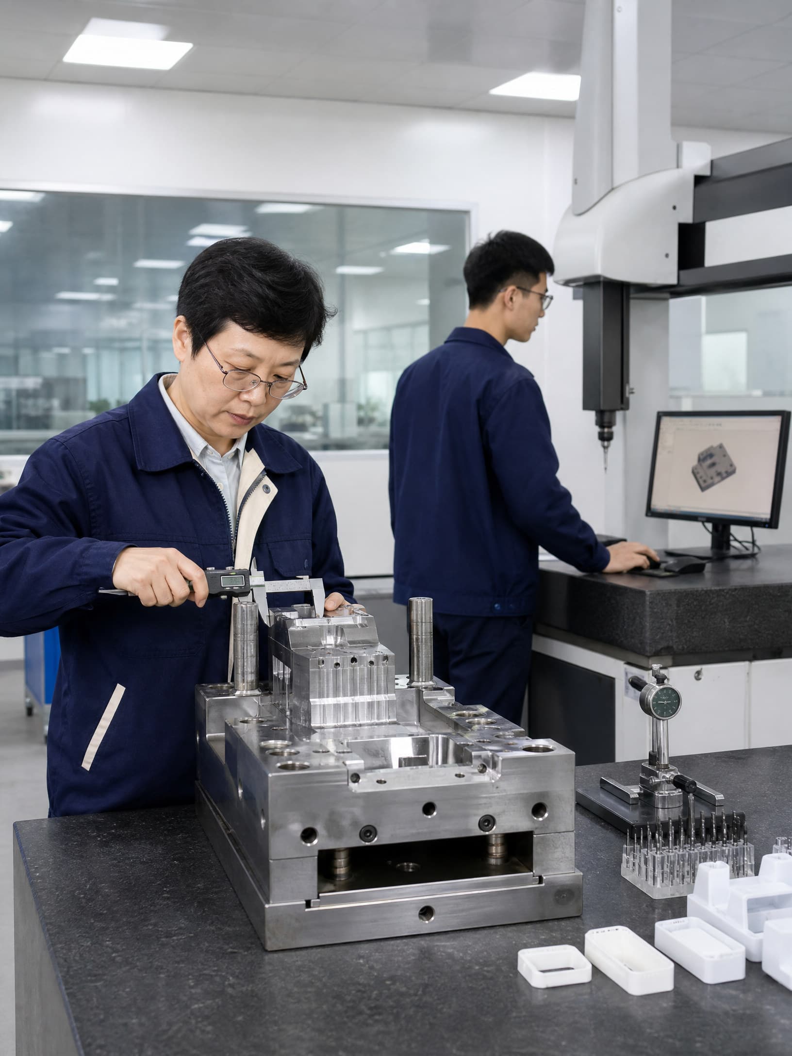
Request configuration-traceable sample evidence. Reports should identify part revision, mold and cavity, resin producer and grade, lot identity, color, molding run, conditioning state, fixture or datum simulation, measured values, visual findings, fit result and deviations. For covers, dimensional checks alone may miss rattle, latch release, seal leakage, fastener torque loss, impact damage or interference with moving equipment. Add the functional checks required by the product owner and machinery risk assessment.
Separate manufacturing evidence from field validation. A supplier can provide DFM, dimensional, material and process records; the equipment maker decides whether exposure, vibration, impact, ingress, guarding, thermal or service-life validation is required. Ask how nonconforming parts, resin substitutions, mold repairs, color changes and inspection-method changes are controlled. InjeForm’s [quality](/quality) page is a natural route for aligning CTQs and records before the quote is finalized.
05
5. Ask supplier questions that expose outdoor-program readiness
Ask for a marked-up DFM that shows the proposed gate, weld-line locations, parting line, shutoffs, slides or lifters, ejection, venting, cooling and likely cosmetic boundaries. Request a quote separating tooling, samples, inspection, environmental or functional testing, packaging and production. Confirm machine fit, cavity balance, cycle assumptions and whether the proposed tool architecture supports seasonal demand and spare-part volumes.
Probe material and process control: how are resin lots, drying and approved substitutions recorded; how are UV stabilizer, color and regrind controlled; how are cavity identity and rejects managed; and what happens after a mold repair? Ask for the maintenance and change-notification route, backup capacity, sample retention, packaging protection and escalation contact. For export programs, clarify tool ownership, data handover, Incoterms, export documents and responsibility for transport damage through the [export molding](/export-injection-molding) discussion.
Set approval gates: requirements and exposure freeze, DFM/material disposition, tool design, T0/T1 sample review, dimensional and fit evidence, required chemical/UV or mechanical conditioning, pilot production, packaging approval and production release. Send the controlled package through [request-a-quote](/request-a-quote) and ask the supplier to list open assumptions. If the cover is part of a regulated or safety-relevant machine, the equipment manufacturer remains responsible for determining applicable legal and validation obligations.
Practical takeaway
Before you move
to the next review.
- Provide controlled cover CAD and drawings with frame, hinge, latch, fastener, gasket, insert, clearance and service-access information.
- Map UV, temperature, water, dust, washdown, fertilizer, pesticide, oil, fuel, cleaning and vibration exposure with realistic durations and consequences.
- Review skin, ribs, bosses, gussets, hinge towers, latches, drainage and seal flanges as a load path before approving tool steel.
- Name the exact resin grade, reinforcement, stabilizer, colorant, moisture basis, regrind policy and approved-substitution route.
- Require cavity- and revision-linked dimensional, fit, fastener, exposure, functional, packaging and change-control evidence before production release.
FAQ
Common questions
What should an agricultural equipment cover injection molding RFQ include?
Include the released CAD and drawing, machine interfaces, hinges, latches, seals, fasteners, loads, clearances, service sequence, annual volume, exact field exposures, material direction, CTQs, packaging and required validation evidence.
Which plastic is best for an agricultural equipment cover?
There is no universal best resin. PP, PA/PA-GF or PBT may be starting directions depending on stiffness, impact, moisture, chemicals, UV, temperature, fasteners and electrical interfaces. Approve the exact grade only after part-level review and testing.
How should buyers address pesticide and fertilizer exposure?
Name the formulation or chemical where known, concentration, temperature, contact time, repetition and mechanical stress. Obtain grade-specific compatibility information and test stressed molded features using the product owner’s acceptance criteria.
Do agricultural covers need UV testing?
Outdoor exposure often warrants a defined weathering or UV review, but the method, duration and pass criteria depend on the machine, market and expected life. ISO 4892-2 is a reference for laboratory exposure methods, not an automatic field-life guarantee.
What inspection evidence should precede production release?
Request revision-, cavity- and resin-lot-linked dimensional results plus assembled fit, latch, seal, fastener, clearance and any agreed exposure or impact checks. Close deviations and document material, mold, process and inspection changes before release.
References
Source material
- [1] International Organization for Standardization, ISO 20457:2026 — Plastics moulded parts: Tolerances and acceptance conditions.
- [2] International Organization for Standardization, ISO 4892-2:2013 — Plastics — Methods of exposure to laboratory light sources — Part 2: Xenon-arc lamps.
- [3] ASTM International, ASTM D543 — Standard Practices for Evaluating the Resistance of Plastics to Chemical Reagents.
- [4] BASF, Ultramid® and engineering plastics technical information, including processing and material data.
- [5] International Organization for Standardization, ISO 9001:2015 — Quality management systems.
This guide is general information for early procurement and engineering discussion. It does not replace product-specific DFM, qualification, validation, regulatory assessment or legal advice.