
An EV battery plastic component may sit outside a module, between conductive parts, inside a serviceable cover, or beside a thermal-management path. A cover may need stiffness, sealing support and controlled appearance; an isolator may need stable geometry and electrical separation; a clip may carry repeated assembly or retention loads; and a thermal-interface carrier may need to hold pads, sensors or shields in a defined position. Treating all four as a generic plastic-part quote can hide the risks that determine pack assembly, environmental durability and release evidence.
For procurement, source the component and its evidence boundary together. Give each bidder the controlled mating geometry, temperature and fluid exposures, electrical keep-outs, material direction, annual demand, tooling assumptions, CTQs and validation route. The responsible battery or vehicle engineering team must define the protection objective and applicable customer or market requirements; the molding supplier can then propose manufacturable geometry, resin grades, gates, tool actions, inspection and process controls. InjeForm’s [automotive and mobility application](/products/automotive-mobility) page provides a relevant starting point, while [request a quote](/request-a-quote) can carry the controlled RFQ package.
Buying rule: do not award an EV battery component on resin family or unit price alone. Compare the exact part function, environment, tool concept, traceability and component-level evidence required for release.
01
1. Split the EV battery RFQ by component function
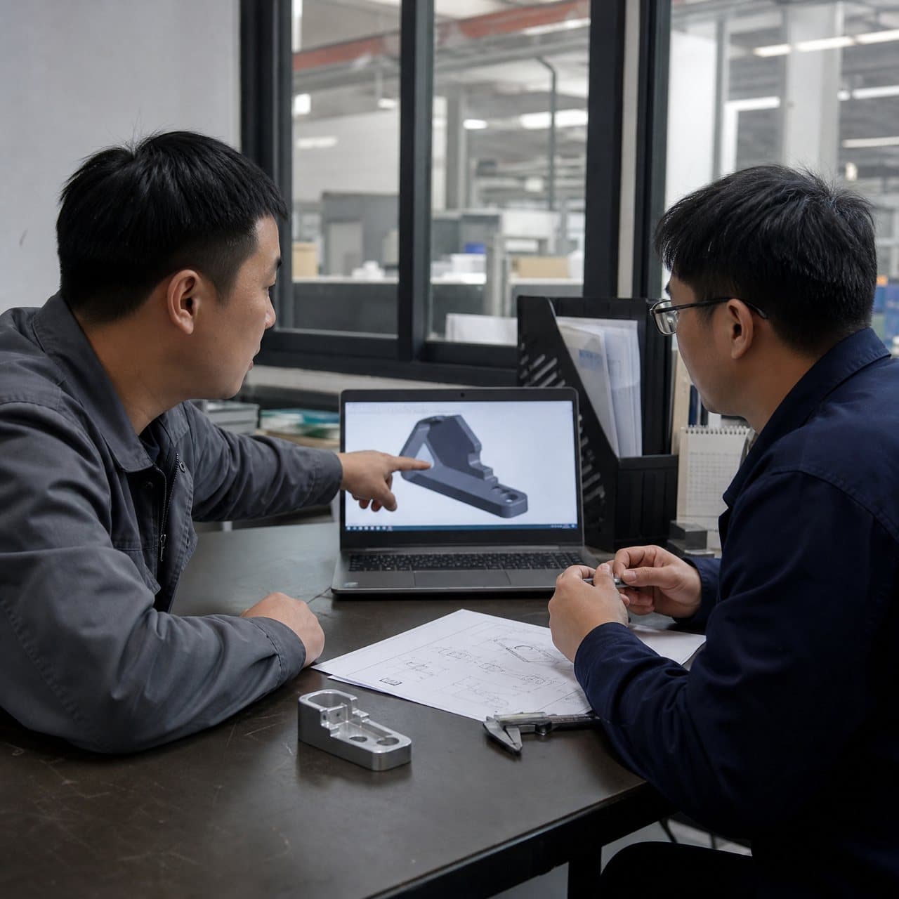
Name the component’s role before asking for a mold price. For a cover, show the gasket land, fastener pattern, service openings, vent or pressure-relief interfaces where defined, cosmetic boundaries and adjacent housing. For an isolator, show the busbar, terminal, cell, module, sensor or shield it separates, plus the minimum electrical keep-outs and assembly direction. For a clip, define insertion, engagement, removal, service cycles and the structure that receives its load. For a thermal-interface carrier, identify the pad, heat spreader, sensor, coolant-adjacent feature or electronics envelope it locates.
Supply the complete interface stack instead of an exterior STEP file alone: cell or module envelope, busbars, terminals, fasteners, gasket, mating housing, cooling hardware, harnesses, sensors, shields and neighboring molded parts. Mark primary datums, no-contact zones, sealing surfaces, clip hooks, isolation barriers, thermal contact surfaces and appearance zones. State whether the part is molded alone, insert molded, assembled later, overmolded or used as a replaceable service item.
Describe the use condition in measurable terms where the product team has defined them: continuous and transient temperatures, humidity, splash or immersion, road salt, coolant, oils, cleaners, electrolyte-related exposure, vibration, shock, UV, dust, pressure and expected service life. Avoid asking for a generic ‘EV-grade’ material or certification. The applicable vehicle, battery, customer and market requirements determine the final acceptance basis.
| Component | RFQ inputs to provide | Evidence to compare |
|---|---|---|
| Battery cover | Mating housing, gasket, fasteners, service sequence, sealing intent, appearance zones and mounting loads | DFM sections, flatness and interface dimensions, seal or leak method, visual standard and cavity-linked inspection |
| Electrical isolator | Conductive-part locations, creepage and clearance requirements, dielectric barriers, temperature and contamination assumptions | Exact resin grade, molded dimensions, flash and warp review, electrical test plan owned by the product authority |
| Retention or service clip | Insertion direction, hook engagement, mating tolerance, installation/removal force and service-cycle expectation | Clip geometry, fiber orientation, insertion and retention checks, durability method and failure disposition |
| Thermal-interface carrier | Pad or spreader geometry, compression or location intent, heat-source envelope, sensor and coolant clearances | Position and flatness evidence, material conditioning, assembly check and thermal validation defined by the system owner |
02
2. Resolve cover, isolator and clip geometry before steel
Battery covers often fail sourcing review at interfaces rather than on their broad panels. Review wall transitions, ribs, bosses, screw towers, gasket grooves, weld lines, parting lines, ejector locations and warpage against the mating housing. A cover that looks acceptable in isolation can leak, bind during service, transmit clamp load unevenly or interfere with a cell or harness when assembled. Use InjeForm’s [DFM and mold-design service](/injection-mold-design-dfm) to record each proposed gate, slide, lifter, shutoff and ejection trade-off before steel is cut.
Isolators need an electrical and mechanical section review. Identify the conductive parts that must remain separated, the surfaces that locate the isolator, the possibility of flash or burr-like vestige at an interface, and any pressure, vibration or assembly load that can move the part. Creepage and clearance values depend on the product standard and operating conditions; the molding supplier can highlight geometry and measurement risks, but the responsible electrical or product authority must set the acceptance values and validation route.
Treat clips as functional springs, not incidental tabs. Define the load path, insertion speed, engagement confirmation, removal access, repeated-service expectation and consequence of partial engagement. A clip root, hook or cantilever can be affected by gate location, weld line, glass-fiber orientation, notch sensitivity, temperature and molding variation. Request a marked-up risk review and functional sample plan rather than accepting a generic ‘snap-fit ready’ statement.
03
3. Choose the exact resin against thermal and environmental duty
Use the application data as a starting screen, not a final approval. PA or PA-GF may be considered for stiff functional features, PBT for dimensional stability around electrical interfaces, and PC/ABS for suitable impact and cosmetic balances. PP can suit some lightweight, chemically resistant or hinged components. The exact commercial grade, reinforcement, colorant, additive package, moisture condition, shrinkage data and processing window must be evaluated against the part and its environment.
Compare candidates against the failure mode each component can experience. For covers, examine creep at fasteners, gasket compression, warpage and chemical exposure. For isolators, examine dimensional stability, dielectric requirements and contamination or flash control. For clips, examine fatigue, weld-line strength, low-temperature impact, creep and fiber direction. For thermal-interface carriers, examine flatness, heat exposure, pad compatibility and dimensional retention after conditioning. Glass reinforcement may improve stiffness but can increase anisotropic shrinkage, tool wear and directional behavior.
Ask for the resin producer, exact grade, current technical data sheet, lot traceability, drying basis where applicable, approved substitutions, regrind policy and color or additive identity. Material-level classifications or datasheet values are not finished-pack approval. If a customer requires flame, electrical, chemical, thermal or environmental testing, define the method, specimen or molded-part condition, severity, acceptance criterion and responsible approver. A thermal-runaway or vehicle-level safety conclusion cannot be inferred from one plastic coupon or a supplier label.
| Decision factor | Cover | Isolator | Clip or carrier |
|---|---|---|---|
| Primary risk | Seal support, flatness, fastener load and warpage | Separation, flash, contamination and dimensional stability | Retention, fatigue, creep, pad location or assembly damage |
| Material questions | Temperature, chemicals, color, stiffness and joining method | Exact grade, electrical behavior, moisture and temperature | Impact, weld line, fiber direction, repeated load and conditioning |
| Process evidence | Cavity-linked flatness and interface report; leak or seal check where specified | Flash/warp inspection and product-defined electrical validation | Insertion/retention results, durability plan and failure analysis |
| Do not assume | A gasket groove proves an ingress rating | A resin family proves insulation compliance | A nominal snap dimension proves service life |

04
4. Build inspection evidence around thermal and environmental interfaces
Create a CTQ map that follows the assembly. Cover CTQs may include sealing-land profile, mounting-hole position, flatness, clip or latch location, clearance and cosmetic boundaries. Isolator CTQs may include conductive-part spacing, locating features, barrier height, flash limits and retention. Clip CTQs may include hook engagement, free position, root geometry and insertion or retention behavior. Thermal-interface-carrier CTQs may include pad pocket, sensor location, contact flatness and assembly compression or seating features.
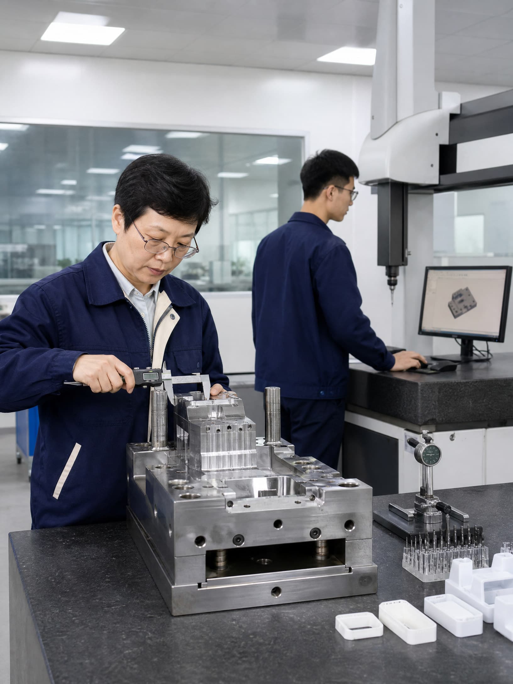
Make the inspection condition part of the requirement. State datums, fixture simulation, part conditioning, time after molding, temperature and humidity where relevant, measurement equipment, sampling, cavity identity and reaction plan. A CMM report can establish geometry, while a functional gauge, assembled fit check, insertion-force test, retention test, seal or leak test, insulation test or thermal evaluation may answer a different question. The customer quality plan should determine which combination is required.
Request reports that connect evidence to configuration: part revision, tool and cavity, resin producer and lot, molding run, color or additive basis, conditioning, fixture, actual values, deviations and disposition. Separate material screening, molded-component results and assembled-pack validation. InjeForm’s [quality](/quality) page can support the evidence discussion, but a supplier quality certificate does not replace the product owner’s validation or regulatory responsibilities.
05
5. Compare suppliers by program readiness, not only quoted piece price
Normalize every bid around the same scope. Ask suppliers to state resin and source, cavity count, gate and runner concept, parting line, slides or lifters, mold steel assumptions, machine fit, insert loading, estimated cycle, inspection scope, samples, secondary operations, packaging, exclusions, tooling ownership and delivery assumptions. Treat capacity, tool life, yield, timing and cost as project assumptions until confirmed against the final geometry, grade, tool and demand profile.
Ask questions that expose evidence and change-control maturity. Who controls resin drying and lot identity? How are cavity, regrind, color and nonconforming parts segregated? How will the supplier detect a missing or reversed insert? What happens after a tool repair, resin substitution, gate change, mold transfer or inspection-method change? Can the supplier provide a DFM review, trial plan, sample report, control plan, calibration status and corrective-action route? For a cross-border program, also clarify packaging, Incoterms, export documents, retained samples and escalation contacts.
Set release gates in writing: requirements freeze; material and DFM disposition; tool-design approval; T0/T1 or engineering sample review; dimensional and functional evidence; thermal or environmental validation where applicable; pilot or production-intent review; and shipment release. If the component contributes to electrical isolation, sealing, thermal management or vehicle safety, the product and vehicle authorities must decide applicable validation and market obligations. Use [request a quote](/request-a-quote) to send the controlled package and ask InjeForm to identify assumptions rather than silently filling gaps.
Practical takeaway
Before you move
to the next review.
- Separate covers, isolators, clips and thermal-interface carriers by function, interfaces, loads, environmental exposure and required evidence before requesting quotes.
- Provide revision-controlled CAD, drawings and mating-part data with datums, electrical keep-outs, sealing features, thermal interfaces, service access and CTQs marked.
- Compare exact resin grades, reinforcement, colorants, moisture controls and approved substitutions against temperature, chemicals, vibration, electrical and thermal duties.
- Require cavity- and configuration-traceable inspection and functional evidence for flatness, fit, retention, isolation, sealing or thermal-interface features as applicable.
- Agree DFM, tooling, material, validation, change-control, packaging, ownership and production-release gates before awarding the EV battery component program.
FAQ
Common questions
What should an EV battery plastic component RFQ include?
Include the component function, controlled CAD and drawings, mating parts, battery and conductive-part envelopes, temperature and environmental exposures, exact material direction, annual volume, CTQs, inspection method, validation route, packaging and approval gates.
Which plastic is best for an EV battery cover or isolator?
There is no universal best resin. PA or PA-GF, PBT, PC/ABS, PP and other grades may be considered depending on geometry and duty. Select the exact grade against temperature, chemicals, electrical requirements, creep, impact, moisture, shrinkage and customer validation.
How should molded battery clips be tested?
Define insertion direction, engagement confirmation, installation and removal method, force or retention targets, service-cycle expectation, mating tolerances and temperature conditioning. Use dimensional checks plus the functional and durability tests required by the component or vehicle program.
Does a material flame or electrical rating approve an EV battery component?
No. A material classification or datasheet result applies to defined specimens and conditions. It does not by itself prove the molded component’s sealing, isolation, thermal, impact, vehicle or market compliance. Confirm the product-specific test and approval scope.
What supplier evidence should buyers request before production release?
Request approved DFM and tool assumptions, exact material identity and traceability, cavity-linked dimensional results, functional checks for the relevant component, environmental or thermal evidence where required, open-risk closure, change control and written release authority.
References
Source material
- [1] UL Solutions, Battery Enclosure Thermal Runaway (BETR) Evaluation.
- [2] U.S. National Highway Traffic Safety Administration, FMVSS No. 305: Electric-powered vehicles: electrolyte spillage and electrical shock protection.
- [3] International Electrotechnical Commission, IEC 60664-1, Insulation coordination for equipment within low-voltage systems.
- [4] International Electrotechnical Commission, IEC 60068-1, Environmental testing — Part 1: General and guidance.
- [5] International Organization for Standardization, ISO 20457:2026, Plastics moulded parts — Tolerances and acceptance conditions.
This guide is general information for early procurement and engineering discussion. It does not replace product-specific DFM, qualification, validation, regulatory assessment or legal advice.