
A fluid connector injection molded part is a pressure boundary and an assembly interface, not merely a plastic fitting. Its port, barb, thread, O-ring land, gasket face, weld line, insert and mating axis can each influence whether the finished system seals. A quote based only on the connector’s external CAD, resin family and annual volume leaves the supplier to infer pressure, media, temperature, assembly torque, seal compression and test responsibility.
Qualify the part as a controlled package: released geometry, mating hardware, sealing concept, operating envelope, exact material direction, process assumptions, inspection plan, pressure method and leak-test evidence. InjeForm’s [industrial equipment application page](/products/industrial-equipment) identifies pump, valve and fluid-handling component housings as a relevant application. Use the [request-a-quote](/request-a-quote) route with the actual interface and test inputs, rather than asking a molder to approve an isolated plastic shape.
Buying rule: a passing dimensional report does not prove a fluid connector is leak-tight. Release decisions should link the seal interface, pressure condition, fluid, temperature, fixture, test method and material configuration to the evidence.
01
1. Define the fluid connector as an assembled pressure boundary
Start the RFQ with the connector’s job in the fluid system. Identify whether it is a hose barb, push-to-connect body, threaded adapter, manifold port, quick-connect shell, sensor port or a molded housing that carries a separate fitting. Provide the mating tube, hose, insert, valve, sensor, clamp, O-ring, gasket, washer and fastener data that establish the real stack. Mark the sealing land, lead-in, thread or barb, retention feature, pressure cavity, vent path and any surface that must remain free of gate vestige or parting-line mismatch.
State the operating envelope without turning a preliminary number into a guarantee: internal pressure range, pressure spikes, vacuum or reverse pressure, temperature range, fluid or gas, concentration, exposure time, duty cycle, installation torque, hose material, assembly force and expected service life. Distinguish working pressure from proof, burst or qualification conditions. The product owner should define the governing specification and safety margin; the molding supplier can review geometry, material and process implications but should not invent a system rating from a polymer name.
Include volume by phase, assembly location, inspection access, packaging orientation, cavity expectations and whether the tool may transfer. Ask bidders to separate assumptions for inserts, secondary machining, thread chasing, deburring, cleaning, assembly, pressure testing, labeling and pack-out. Link every requirement to the controlled part revision and mating-component revision so a later leak result can be traced to the configuration that was actually tested.
| RFQ input | Evidence or file to provide | Risk addressed |
|---|---|---|
| Pressure and media | Working, proof and cycle conditions; fluid or gas identity, temperature and exposure duration | Material swelling, cracking, permeation or an unrepresentative test condition |
| Sealing interface | Sectioned CAD, O-ring or gasket data, mating bore or tube, compression or torque requirement if defined | Under-compression, over-compression, extrusion, misalignment or assembly damage |
| Mating stack | Hose, insert, clamp, valve, sensor, fastener and assembly sequence with revisions | A connector that passes a free-state check but fails in the installed system |
| Acceptance basis | CTQs, datums, visual boundary, pressure method, leak limit and sample plan | Disagreement about what constitutes a qualified part |
| Production scenario | Forecast, cavity plan, resin source, packaging and traceability needs | Evidence from a trial configuration that cannot represent routine supply |

02
2. Review sealing interfaces and mold risks before steel
Treat the sealing interface as a functional geometry, not a generic diameter. For an O-ring land, identify the gland dimensions, squeeze direction, stretch or compression assumptions, corner radii, extrusion gap, assembly chamfer and surface condition required by the product design. For a gasket face, define flatness, sealing width, bolt or clamp pattern and the mating surface. For a barb, specify hose material, insertion direction, retention feature, pull-off concern and whether the barb itself is the pressure boundary. The responsible product engineer should own the seal design and acceptance limits; the molder should show how the proposed tool can form and inspect it.
Ask for a marked-up DFM review of gates, weld lines, vents, shutoffs, slides, lifters, ejectors and parting lines around the pressure path. A weld line near a thin sealing land, flash across an O-ring groove, a gate vestige on a gasket face or ejection distortion at a port can create a functional risk even when the overall outline is in tolerance. Use InjeForm’s [DFM and mold-design service](/injection-mold-design-dfm) to keep these decisions visible before tooling, and require the supplier to identify which features are adjustable and which require a design change.
Consider how the molded part will be held during inspection and assembly. A round connector can rotate in a gauge; a flexible barb can deflect under clamp load; a threaded port can read differently after cleaning or insert installation. Define datum simulation, support, torque, assembly lubricant if permitted, seal conditioning and the state in which the dimension or functional check governs. Published seal guidance can inform the design review, but the customer’s mating parts, media and pressure cycle determine the final qualification route.
03
3. Select material from pressure, media and process evidence
Use the exact commercial grade as the starting point, not only PP, PA, PBT, POM or another family label. InjeForm’s industrial application data lists PA, POM, PP and PBT as possible directions for industrial and fluid-related parts, but the suitable choice depends on the connector’s media, temperature, pressure, assembly load, dimensional stability, permeability, stress-crack resistance and required service interval. Resin-maker data and customer validation remain the basis for approval.
Compare candidates against the failure modes at the actual interface: creep under clamp or thread load, moisture-driven dimensional change, chemical swelling, hydrolysis, stress cracking, weld-line strength, fiber orientation, permeation, low-temperature impact and post-mold shrinkage. A filled grade may increase stiffness yet change anisotropic shrinkage, surface condition and tool wear. A material or colorant change can alter flow, weld lines, port position and seal compression; define whether it triggers renewed leak or pressure qualification.
Request the producer, exact grade, reinforcement, color or additive route, lot identity, technical data sheet, drying basis where applicable, approved substitutions, regrind policy and any customer-required declarations. Do not treat a data-sheet pressure value, food-contact statement, chemical-resistance chart or broad ‘engineering plastic’ description as proof for the finished connector. Product-specific testing should use the molded geometry, the intended mating parts and the agreed fluid, temperature and pressure conditions.
| Preliminary direction | Potential reason to investigate | Evidence needed before approval |
|---|---|---|
| PP | Lightweight or chemically resistant fluid-related geometry where the exact grade supports the duty | Grade-specific pressure, temperature, media, creep and dimensional evidence |
| PA / PA-GF | Stiff ports, brackets or functional housings where strength and heat direction matter | Moisture conditioning, fiber orientation, weld-line, chemical and seal-interface checks |
| POM | Low-friction precision features or valve-adjacent components where compatible | Media compatibility, temperature, stress-crack, dimensional and pressure-cycle evidence |
| PBT | Stable geometry near electrical or equipment interfaces where the grade fits | Exact-grade thermal, chemical, dimensional and pressure-boundary assessment |
04
4. Separate dimensional inspection from pressure and leak testing
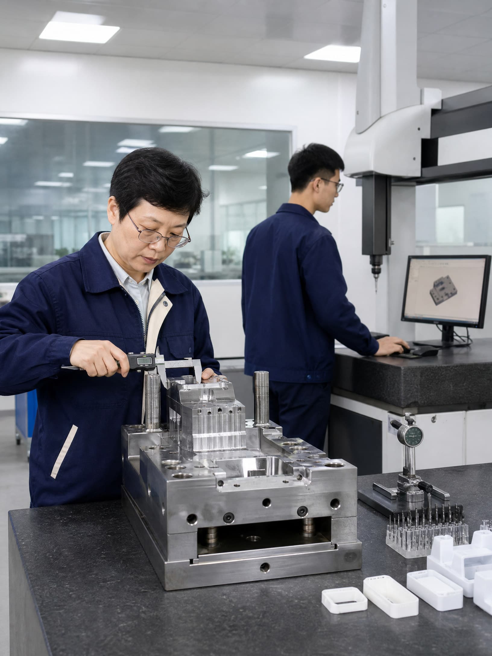
Build the inspection plan around the way the connector fails. Dimensional checks may cover port diameter, barb profile, thread form, O-ring land, gasket face, insert position, wall section, shutoff and mating axis. Identify datums, part condition, fixture, measurement method, cavity identity and sample quantity. CMM or optical measurement can document position and profile, while a mating gauge, hose pull check, torque check or assembled fit check may better represent the interface. A dimensional pass is evidence for those characteristics only; it is not a leak result.
Define pressure testing with enough detail to reproduce it: test medium, fill or evacuation procedure, trapped-air controls, temperature, stabilization time, pressure ramp, hold time, fixture sealing method, orientation, monitored volume or pressure change, leak threshold, equipment calibration and failure disposition. Decide whether the test is a proof test, burst test, pressure-decay test, bubble or immersion check, flow test or another method. ISO 1167 addresses resistance to internal pressure for thermoplastics pipe and fittings under specified conditions, but it should not be treated as a universal acceptance method for every molded connector; select the applicable product or customer method.
For production release, request traceable results that identify part revision, tool and cavity, resin lot, molding run, mating hardware, seal lot, fixture, test medium, temperature, pressure profile, duration, measured result and disposition. Explain whether samples were conditioned, assembled once or cycled repeatedly. If pressure or leak performance is safety-relevant, the product owner should set the qualification matrix and laboratory or quality-system requirements. InjeForm’s [quality control](/quality) discussion can help map critical dimensions and functional evidence to the agreed release plan.
05
5. Ask suppliers questions that expose qualification readiness
Ask the supplier to show a sectioned tool concept and risk register for the pressure path. Which gate and weld-line locations are expected? How are vents placed near the last-fill region? How will shutoffs, slides, lifters, inserts and ejection protect the sealing land? What tool-steel, maintenance and adjustment assumptions affect the port, thread or O-ring groove? A useful response distinguishes a preliminary DFM opinion from evidence generated on the approved part and process.
Probe the production controls behind the sample. How are resin drying and lot identity recorded? How are cavity, insert and seal lots linked to the finished connector? What prevents mixed revisions, omitted inserts, flash, contamination or an untested rework condition? Which dimensions are checked every run, which are sampled, and what reaction plan applies after a leak or pressure failure? Ask whether the test fixture seals on the same interface used in the product; a fixture that bypasses the real seal can produce false confidence.
Set written release gates: requirements and mating-part freeze; material and DFM approval; tool-design review; T0 or T1 dimensional review; assembled sealing check; pressure and leak qualification; pilot or run-at-rate evidence; control-plan approval; and production release. Clarify tool ownership, change notification, test-record retention, packaging cleanliness and export responsibilities. Send the full controlled package through [request a quote](/request-a-quote), and ask the supplier to list exclusions rather than burying them in a low unit price.
Practical takeaway
Before you move
to the next review.
- Provide sectioned connector CAD, mating hose or fitting data, seal and insert revisions, assembly sequence, media, temperature and pressure conditions.
- Mark sealing lands, threads, barbs, pressure cavities, datums, CTQs, permitted gate areas and surfaces that must be free of flash or vestige.
- Compare exact resin grades using media compatibility, creep, moisture, shrinkage, weld-line, permeability, temperature and seal-interface evidence.
- Define dimensional, assembled, pressure and leak-test methods with fixture, medium, temperature, ramp, hold, threshold, calibration and disposition rules.
- Release only configuration-traceable samples with cavity, resin, seal, mating hardware, test records, open risks and change-control responsibilities documented.
FAQ
Common questions
What should a fluid connector injection molding RFQ include?
Include controlled connector CAD and drawing data, section views, mating hose or fitting, seal and insert information, media, temperature, working and proof pressure, volume, material direction, CTQs, inspection method, leak-test method and production-release evidence.
Does a dimensional inspection prove a molded fluid connector will not leak?
No. Dimensions can show conformity of selected features, but leak performance depends on the assembled seal, fixture, material, pressure, medium, temperature, conditioning and test method. Use dimensional and functional evidence together.
Which plastic is best for a pressure-bearing fluid connector?
There is no universal best polymer. PP, PA, POM or PBT may be investigated for different duties, but the exact grade must be assessed against the fluid, temperature, pressure, creep, chemical exposure, shrinkage, seal system and part-level validation.
What is the difference between a proof test and a leak test?
A proof test checks behavior at a defined pressure condition, while a leak test detects leakage using a specified method and threshold. The product owner should define whether either test, both tests or a different qualification method applies to the connector.
What supplier evidence should precede production release?
Request approved DFM and material records, tool and cavity identity, dimensional results, assembled seal checks, pressure and leak data, fixture and calibration details, resin and seal traceability, deviations, control-plan records and change-control commitments.
References
Source material
- [1] International Organization for Standardization, ISO 1167-1: Thermoplastics pipes, fittings and assemblies for the conveyance of fluids — Determination of the resistance to internal pressure — Part 1: General method.
- [2] International Organization for Standardization, ISO 20457: Plastics moulded parts — Tolerances and acceptance conditions.
- [3] ASTM International, ASTM D1599: Standard Test Method for Resistance to Short-Time Hydraulic Pressure of Plastic Pipe, Tubing, and Fittings.
- [4] Parker Hannifin, O-Ring Handbook, sealing design and installation guidance.
- [5] BASF, Ultramid and engineering plastics technical information for processing and material selection.
This guide is general information for early procurement and engineering discussion. It does not replace product-specific DFM, qualification, validation, regulatory assessment or legal advice.