
A family mold produces two or more different plastic parts in the same molding cycle. That can be useful when an assembly consumes the parts in stable proportions, when the components share a material direction, and when one coordinated tool is easier to manage than several separate tools. It is not automatically the lowest-risk or lowest-cost option. Different part volumes, flow lengths, wall sections, cosmetic requirements and demand patterns can make a shared tool difficult to balance.
The right buyer question is not simply whether several parts can fit inside one mold. It is whether the proposed family mold can deliver acceptable parts together, in the quantities the programme actually consumes, with a qualification and change-control plan that remains workable.
Treat a family mold as a combined product-and-supply decision: the geometry must work in one tool, and the parts must remain commercially useful in the same production ratio.
01
Start with the part family and the assembly demand
List every proposed member of the family and define its function, material, colour, annual demand, launch demand, spare demand and assembly quantity. A housing, cover, clip and seal carrier may be related in one assembly, but that does not mean they should be forced into a common tool. The family relationship should be visible in the product architecture and the consumption plan, not only in a CAD layout.
Demand ratio is a central screening test. If the assembly needs one of each part, a one-to-one output ratio may be practical. If one component is replaced more often, sold separately, or shared with another product, the family tool can create excess inventory of the lower-demand members. Model at least launch, steady-state and service scenarios before treating a shared tool as a saving.
02
Check geometry and process compatibility before layout approval
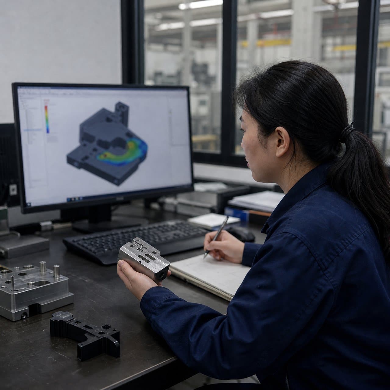
A family mold has to accommodate different projected areas, shot volumes, flow lengths, wall sections and shrinkage behaviour. The parts do not need to be identical, but they need a credible common processing window. A proposed layout should show gate locations, runner paths, cavity orientation, parting direction, draft, ejection and cooling intent for every member. Mold-flow analysis may help compare filling and packing behaviour, but the assumptions should be recorded rather than presented as a guarantee.[1]
The material direction deserves special attention. Different resins, colours or filler systems can require different melt temperatures, drying controls, shrinkage assumptions or cosmetic standards. A family mold using one resin family still needs review of grade, colour and regrind policy. If one part needs a materially different process window, separate tooling or a replaceable insert strategy may be more proportionate than a forced common cycle.
03
Use a decision table to compare the shared-tool case
The table below is a scoping aid, not a substitute for a part-specific DFM review. Ask the toolmaker to explain how the proposed design addresses the highest-risk row for each component. A low tooling price is not comparable if it omits balancing work, sampling, de-gating, inspection or the handling needed to separate different parts.
| Decision area | Family mold may fit | Separate tools may be safer | Evidence to request |
|---|---|---|---|
| Part relationship | Components are assembled together and consumed in predictable proportions | Parts have independent demand, service channels or different revision timing | Assembly quantity map and demand-ratio scenario |
| Material and process | Same resin direction and a reasonably overlapping processing window | Different resins, colours, drying needs or heat history dominate | Material grades, process assumptions and risk review |
| Filling and packing | Runner and gate concept can fill and pack each cavity without unacceptable compromise | One cavity is consistently the limiting or over-packed member | Flow study or engineering rationale with cavity-specific risks |
| Cooling and ejection | Cooling time and release direction can be coordinated | One part needs much longer cooling or a different release mechanism | Cooling concept, ejection layout and cycle-time basis |
| Change control | The family is mature and changes are expected to be coordinated | One part is likely to change independently or frequently | Insert/change strategy and commercial change assumptions |
04
Design gates, runners, cooling and ejection as one system
Gate and runner choices affect fill balance, weld-line locations, vestige, pressure demand, material handling and the appearance of each part. Do not approve a family layout from a top view alone. Review the flow path to each cavity, the expected gate evidence, the runner-material policy and whether the proposed system supports the actual resin and production pattern. Hot-runner and cold-runner options can each be reasonable; the comparison should include maintenance, colour changes, start-up practice and gate requirements rather than only initial mold price.[2]
Cooling should be checked around the thickest or most distortion-sensitive features in every cavity. The cycle is constrained by the member that cannot be released safely, while an aggressive cycle can leave another member under-cooled. Ejection also needs cavity-specific attention: small clips, deep ribs, textured faces and cosmetic surfaces may need different pin, sleeve, stripper or lifter choices. General design guidance treats draft, ejection, wall transitions and cooling as connected decisions, so a late isolated fix may move the risk elsewhere.[3]

05
Plan qualification around each part, not only the assembled set
A family mold should be qualified as a collection of parts and as a production event. The first-article plan should identify dimensions, appearance criteria, material evidence, cavity or component identification, sample quantities and the process conditions used to make the samples. A complete assembly sample can hide a dimensional or cosmetic problem in an individual component, so inspect each member against its own drawing and critical-to-quality list.
Ask how the supplier will identify parts during sampling and how out-of-specification members will be contained. The acceptance plan should define what happens if one cavity meets requirements while another does not. Cavity pressure or other process monitoring may be useful where the programme calls for it, but the chosen evidence should match the risk and should not be promised without an agreed method.[4]
06
Make engineering changes and ownership explicit in the RFQ
A change to one family member can affect the runner balance, cooling layout, ejection, cavity steel and output ratio of the whole tool. Before award, ask which areas are common, which are part-specific, whether inserts can isolate future changes, and how a revision to one component will be quoted and approved. Tool ownership, spare inserts, maintenance records and transfer data should also be stated in the commercial package rather than inferred from a tooling invoice.
An RFQ should request the proposed cavity layout, parting lines, gates, runners, cooling concept, ejection concept, cycle assumptions, sample scope and open risks. Use InjeForm's process and quality discussions to align the DFM review with inspection and production evidence, then send the current CAD, drawings, material direction, demand scenarios and required routes through the quote request.

Practical takeaway
Before you move
to the next review.
- Map every family member to its function, assembly quantity, forecast, spare demand and expected revision schedule.
- Confirm material, colour, drying, shrinkage and cosmetic requirements are compatible with one proposed process window.
- Request a cavity layout showing gates, runners, parting lines, cooling intent and ejection for each component.
- Compare output ratios with real demand scenarios, including launch, steady-state, service and scrap containment needs.
- Define individual part CTQs, inspection evidence, sample identification and the disposition of a failed member.
- Document insert strategy, change-control responsibilities, tool ownership, spare components and transfer records before award.
FAQ
Common questions
Is a family mold always cheaper than separate molds?
No. It may reduce the number of tool bases or coordinate a matched set, but the total decision also includes balancing work, cooling, ejection, inspection, inventory exposure, maintenance and engineering-change risk. Compare the full scope rather than the initial mold price alone.
Can different plastic parts use different materials in one family mold?
Sometimes a tool concept can accommodate different material plans through inserts or separate runs, but a single shot normally needs a compatible process window. Different resins, drying requirements, temperatures or shrinkage behaviour should trigger a specific feasibility review rather than an assumption that the parts can share one cycle.
How should buyers handle unequal demand between family members?
Build a ratio model that separates assembly demand, standalone sales, service demand and scrap. If the tool repeatedly creates surplus of one member, price the inventory and storage effect. Separate tools, modular inserts or a different production sequence may be better even when the family layout appears technically possible.
What should be approved before a family mold is manufactured?
Approve the revision-controlled part data, family relationship, material direction, cavity layout, gate and runner concept, cooling and ejection intent, demand assumptions, sample and inspection plan, and the change-control and ownership terms. Keep unresolved assumptions visible in the approval record.
References
Source material
- [1] Autodesk, “Moldflow Design Guide: Injection Molding.”
- [2] Mold-Masters, “Hot Runner Systems and Components.”
- [3] Fictiv, “Injection Molding Design Guide: Best Practices for Molded Plastic Parts.”
- [4] U.S. Food and Drug Administration, “Process Validation: General Principles and Practices.”
This guide is general information for early procurement and engineering discussion. It does not replace product-specific DFM, qualification, validation, regulatory assessment or legal advice.