
Foaming injection molding can reduce the density of a thermoplastic part by creating a controlled cellular structure during molding, but it is not a universal substitute for solid injection molding. For an OEM, the right question is whether the foam process can meet the required stiffness, impact, dimensional, cosmetic, environmental and validation targets at the intended volume. Resin grade, fiber loading, geometry, flow length, venting, gas or chemical foaming route, mold design, processing window and customer specifications all affect the result. Treat any weight, cycle-time, cost or strength figure as project-specific until it is demonstrated on representative parts.
Decision rule: approve a foaming route only when the supplier has shown part-level density, stiffness, impact, dimensional and cosmetic evidence for the released geometry and material—not merely a brochure percentage.
01
What is foaming injection molding, and when does it fit?
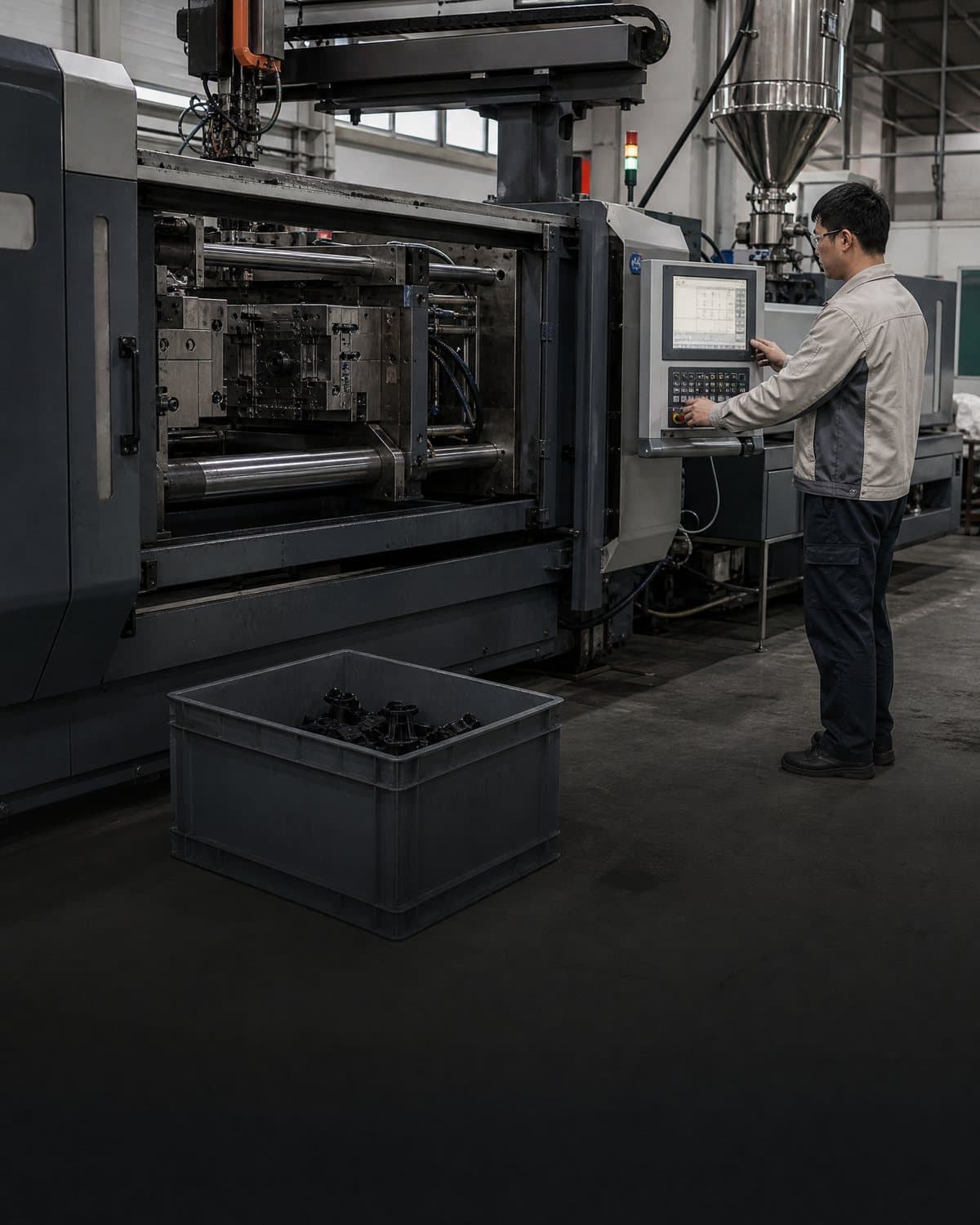
Foaming injection molding introduces a gas or chemical foaming system into a molten thermoplastic so cells form as pressure and temperature change during filling. In microcellular approaches, a supercritical fluid such as nitrogen or carbon dioxide is metered and mixed into the melt; pressure release at the gate nucleates cells, often leaving a denser skin around a lighter core. Other structural-foam routes use a chemical blowing agent or a dedicated low-pressure process. The equipment, material compatibility and control method must be stated in the RFQ rather than assumed from the word foam. [1] [2]
The route is most worth evaluating where lower mass, reduced clamp-force demand, thick-section sink control, large-part handling or integrated ribs and walls could improve the product system. It may fit equipment housings, covers, carriers, brackets, transportation components and other parts in which stiffness comes from section depth and geometry rather than solid material alone. It is less attractive when the part needs a highly uniform cosmetic skin, tight local tolerances, very thin unsupported features, high surface pressure, or a validated solid-material performance envelope that the foam structure could compromise.
A requirement is the performance the released part must meet. A recommendation is the supplier's proposed way to reach it. Do not convert a recommendation such as lower density or a particular gas level into an approved requirement until engineering has defined the load cases, environments, interfaces, inspection method and acceptance criteria.
02
Benefits are real, but lightweighting changes the engineering balance
Lower density can reduce part mass and material consumption, and the lower apparent viscosity or reduced packing demand of some foam processes may change machine and cycle requirements. These effects can improve the business case, but they do not automatically reduce total landed cost. Dedicated dosing equipment, process development, mold venting changes, trials, inspection and qualification can add cost. Volume, resin price, scrap, cycle definition, machine availability, logistics and the customer's approval burden should be included in the comparison.
Stiffness is not the same as strength. A deeper section, ribs, closed cells and a relatively dense skin can preserve useful bending stiffness in some designs, while lower density can reduce tensile, compression, fatigue, fastener pull-out or local impact performance. Fiber reinforcement may raise modulus but can also increase anisotropic shrinkage, flow-direction behavior and warpage. Impact response depends on the resin, cell size and distribution, skin thickness, temperature, notch geometry and loading rate. Require testing on the actual molded configuration where those properties are critical.
Foaming can change shrinkage, warpage, sink behavior, surface appearance and dimensional stability. Cell growth may vary with flow length, gate pressure, venting, temperature, injection speed and gas or blowing-agent level. A foamed part can therefore need different datums, local pads, ribs, draft, radii, venting and cosmetic-zone rules than its solid predecessor. A supplier should explain which design changes are requirements for manufacturability and which are optional recommendations.
| Decision area | Potential benefit | Tradeoff or evidence question |
|---|---|---|
| Part mass and material use | Lower density may reduce mass and resin consumption. | What density and weight were measured on the production-intent geometry, and how stable are they across cavities, lots and process conditions? |
| Stiffness and section design | Cellular structure, ribs and thicker sections may deliver a useful stiffness-to-mass route. | Does the part meet bending, compression, fastening and fatigue loads at the specified temperature and conditioning state? |
| Warp and sink risk | Reduced packing gradients may help some thick-section defects. | What warpage, flatness and sink data exist for the actual gate, vent and wall-thickness design? |
| Tooling and machine demand | Lower filling or clamp-force demand may open machine or tool options in some cases. | Does the mold require new venting, gas-trap controls, surface treatment, pressure control or dedicated dosing equipment? |
| Cosmetics and assembly | A solid skin can protect the internal foam structure. | Will splay, swirl, gloss variation, knit lines, gate marks or local cell exposure affect visible zones, seals or interfaces? |
03
Check fit by resin, geometry, environment and application load
Start with the exact resin family and grade, not the word thermoplastic. The candidate may be an unfilled or fiber-filled PP, ABS, PC-ABS, PA or another grade, but the grade's melt behavior, moisture sensitivity, temperature range, chemical exposure, flame requirements, color system and foaming compatibility must be confirmed. Fiber loading and additives can change cell nucleation, flow, anisotropy, shrinkage and surface quality. A foam process that works for one grade or wall section should not be generalized to another.
Review the load path and interfaces before changing the CAD. Identify fasteners, inserts, clips, hinges, seals, bearing seats, datum pads, impact zones, thermal paths and cosmetic surfaces. Foam may be suitable for broad panels or deep sections while solid bosses, local pads, inserts or overmolded interfaces remain necessary. If the product is pressure-bearing, safety-related, electrically insulating, fluid-sealing or exposed to heat, chemicals, UV, moisture or repeated impact, define the part-level validation evidence before tooling release.
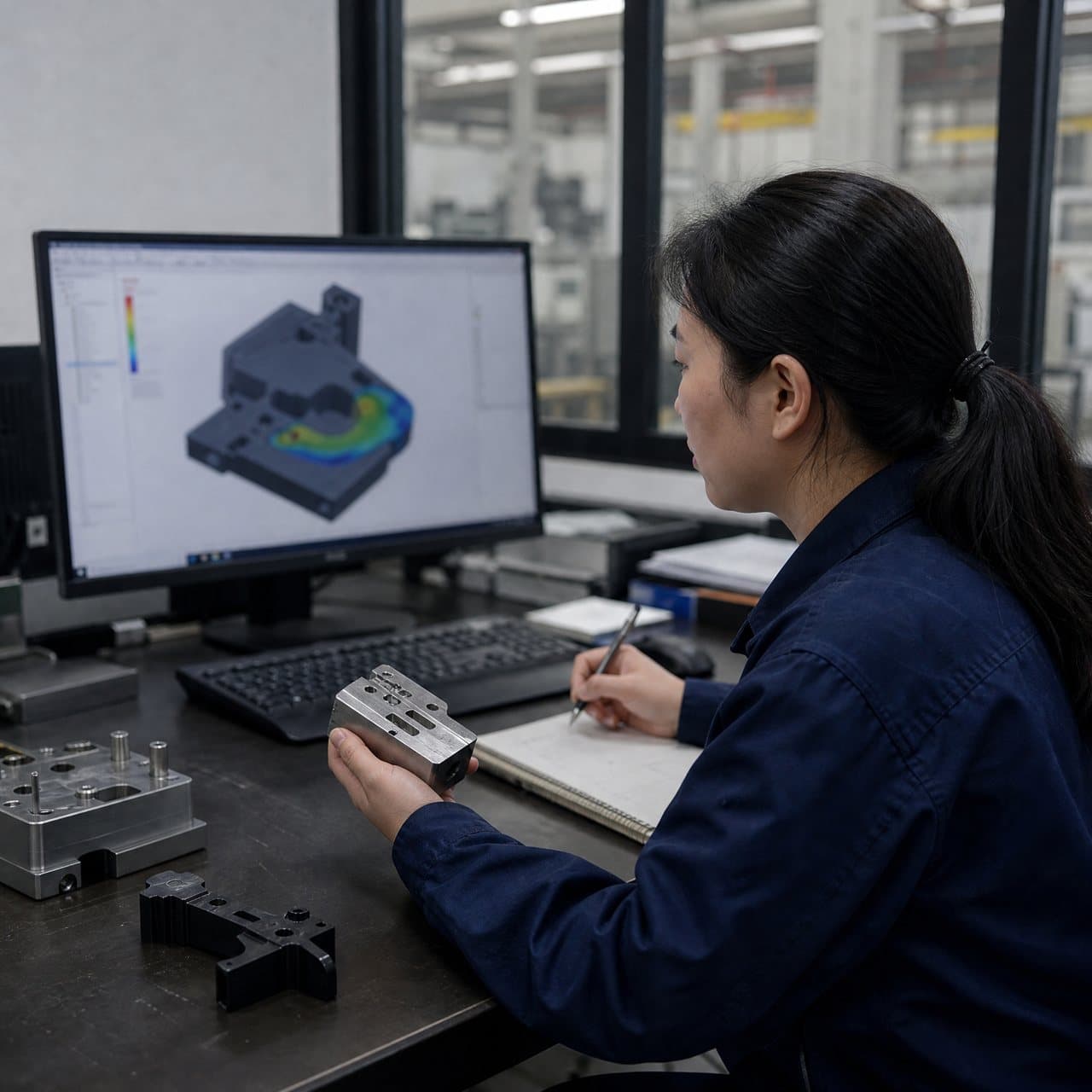
Geometry creates process limits. Long flow paths, thin-to-thick transitions, trapped gas, inadequate venting and abrupt ribs can restrict expansion or create visible and dimensional variation. Use mold-flow or equivalent technical review where justified, and ask the supplier to identify gates, vents, overflow or breathing features, expected skin/core behavior, ejection risks and any regions that cannot achieve the target density. Do not promise uniform lightweighting across the entire part without section-specific evidence.
04
Compare structural foam with solid molding and other lightweighting routes
The comparison should be made against the current solid molded part and any realistic alternative, such as a rib redesign, fiber-reinforced solid resin, gas-assist molding, thermoplastic sandwich construction, thermoforming, compression molding or a metal-to-plastic conversion. The right baseline includes tooling investment, secondary operations, scrap, cycle, inspection, freight, assembly and qualification—not only piece price or mass.
Foam is not automatically the lowest-cost route. It may reduce resin usage or machine demand, but the program may need specialized dosing, controlled venting, additional trials, section-specific testing and tighter process monitoring. Conversely, a modest geometry redesign in conventional molding may deliver the required mass reduction with a simpler supply chain. Procurement should request a like-for-like quotation matrix with assumptions shown and should avoid awarding on a headline percentage that has no defined baseline.
Use a feasibility sample or representative trial before committing to production tooling when the foam process is unfamiliar to the supplier, the part has critical interfaces, or the target density is aggressive. The sample should use the proposed resin, color, reinforcement, gate concept and process route as far as practical. Record deviations from production intent so that a successful prototype is not mistaken for qualification of the final part.
| Route | May fit when | Main buyer caution |
|---|---|---|
| Foaming injection molding | Mass reduction and section efficiency matter, and the product can tolerate a controlled cellular structure. | Validate density distribution, skin/core behavior, cosmetics, interfaces, impact and dimensional repeatability on the actual design. |
| Conventional solid injection molding | The part needs established surface quality, local strength, tight interfaces or a simpler qualification route. | Weight reduction may require ribs, wall changes, a different resin or more packing and cooling; compare total cost and risk. |
| Gas-assist or hollowing route | A controlled hollow section or thick-part core is more valuable than distributed microcells. | Check wall distribution, gas channels, pressure control, appearance and the supplier's specific equipment experience. |
| Thermoforming or compression-based route | The part is large, sheet-like or better suited to a different forming method. | Compare trim, dimensional control, inserts, cycle, tooling, assembly and material utilization rather than mass alone. |
05
Set supplier evidence requests and approval gates
At RFQ, provide the controlled CAD and drawing revision, target mass, load cases, environmental conditions, cosmetic zones, annual volume and ramp, resin constraints, color, critical interfaces, target markets and applicable customer specifications. Ask each supplier to name the foam route, equipment or dosing method, proposed material and grade, expected density range, cell or skin assumptions, gate and vent concept, process window, mold changes, inspection plan, trial plan, risks and exclusions. Require the supplier to separate measured results from estimates and to state the baseline used for every claimed benefit.
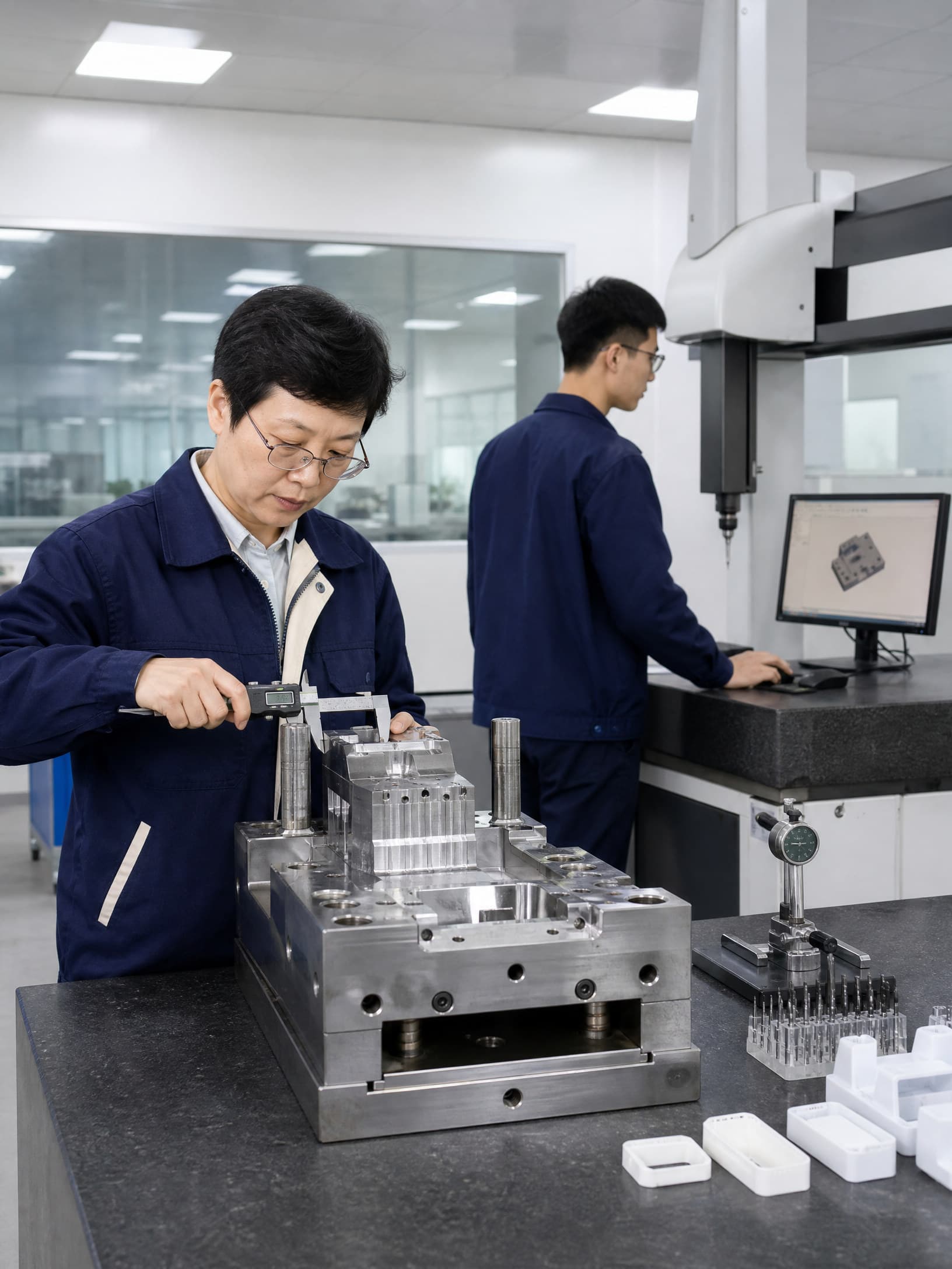
Ask for evidence that matches the decision: part mass and density by defined method; section or skin/core observations where relevant; dimensional inspection and flatness; warpage and post-conditioning checks; tensile, flexural, compression, impact, fatigue or fastener tests selected for the application; cosmetic samples; assembly and seal checks; and process records linking results to resin lot, cavity, machine and settings. ASTM D1622 distinguishes apparent overall density from apparent core density for cellular plastics, which is a useful reminder to define what density means before comparing samples. [3]
Use approval gates. Gate 1 is requirements alignment and feasibility, including a written list of unknowns. Gate 2 is DFM and tooling release after gate, vent, ejection, critical interfaces and validation methods are agreed. Gate 3 is representative trial or first-article review with traceable material and process records. Gate 4 is qualification and customer release for the defined configuration. After release, control changes to resin, color, reinforcement, gas or blowing-agent system, tool, cavity, machine, process window, geometry and inspection method. No supplier claim replaces the product owner's final approval.
Practical takeaway
Before you move
to the next review.
- Define the required mass, stiffness, impact, fatigue, dimensional, cosmetic, environmental and assembly outcomes before selecting a foam route.
- Name the exact resin grade, fiber loading, color and foaming system; ask the supplier to identify compatibility limits and process assumptions.
- Review flow length, wall transitions, ribs, bosses, gates, vents, gas traps, ejection, seals and fasteners on the released geometry.
- Request part-level density, skin/core, dimensional, warpage, cosmetic, mechanical and assembly evidence tied to material lot, cavity and process records.
- Use documented feasibility, DFM/tooling, first-article and qualification gates, with written change control after approval.
FAQ
Common questions
Does structural foam injection molding always reduce part weight?
No. It can reduce density, but achievable weight reduction depends on resin, foam route, flow length, wall thickness, venting, gas or blowing-agent level, temperature, injection conditions and mold design. Poor venting, gas traps or long flow paths can limit expansion. Require a measured comparison on the production-intent geometry rather than accepting a universal percentage.
Is a foamed injection molded part as strong as a solid part?
Not necessarily. A foam design may achieve useful stiffness through section depth, ribs and a denser skin, but lower density can change tensile, flexural, compression, impact, fatigue and fastener performance. Fiber loading and temperature can change the result as well. Define the load cases and validate the finished configuration against the solid baseline where performance is critical.
Will foaming eliminate sink marks and warpage?
No process should be treated as a guaranteed defect eliminator. Foaming may reduce some packing-related sink or warpage mechanisms, but geometry, gate location, venting, cell distribution, cooling, resin, reinforcement and process stability still matter. Review actual flatness, dimensions, sink and cosmetic samples after conditioning and assembly.
What should an OEM ask a structural foam molding supplier before approving tooling?
Ask for the exact foam route, resin grade, color and reinforcement; target density and baseline; gate, vent and mold concept; process window; equipment capability; DFM risks; trial plan; inspection and mechanical validation plan; material and cavity traceability; quotation assumptions; and change-control commitments. Approve tooling only after unresolved risks have an owner and the required evidence and gates are documented.
References
Source material
- [1] Trexel, MuCell microcellular foam injection molding overview
- [2] Trexel, MuCell Processing Guide: Fundamentals, Set-up, Optimization and Troubleshooting
- [3] ASTM D1622, Standard Test Method for Apparent Density of Rigid Cellular Plastics
- [4] Huang et al., Study on the Flow, Foaming Characteristics and Structural Strength of Polypropylene Structural Foam Injection Molding, Polymers
This guide is general information for early procurement and engineering discussion. It does not replace product-specific DFM, qualification, validation, regulatory assessment or legal advice.