
Choose vertical injection molding when the part’s main production challenge is placing, locating or retaining an insert before the mold closes, especially where accessible loading, a shuttle or rotary-table concept may help. Choose horizontal injection molding when the part is principally a molded-plastic component and the production concept is built around automatic ejection, part removal, conveyors, larger tooling or repeated cavities. Both layouts use the same fundamental molding sequence, but the clamping orientation changes access, handling and cell design.[1]
That is a starting answer, not a rule based on part size or annual volume alone. A buyer should decide from the specific part: its insert or no-insert condition, mold mass and envelope, projected area and clamping need, material, permitted handling, downstream inspection and product demand. A vertical machine can be automated; a horizontal machine can mold inserts. The question is which arrangement controls the part’s decisive risk with the least unnecessary complexity.[1][2]
Orientation changes the clamping direction: vertical machines open up and down, while horizontal machines open side to side; both follow the basic injection, holding, cooling, opening and ejection sequence.[1]
01
Choose vertical when insert placement drives the part risk
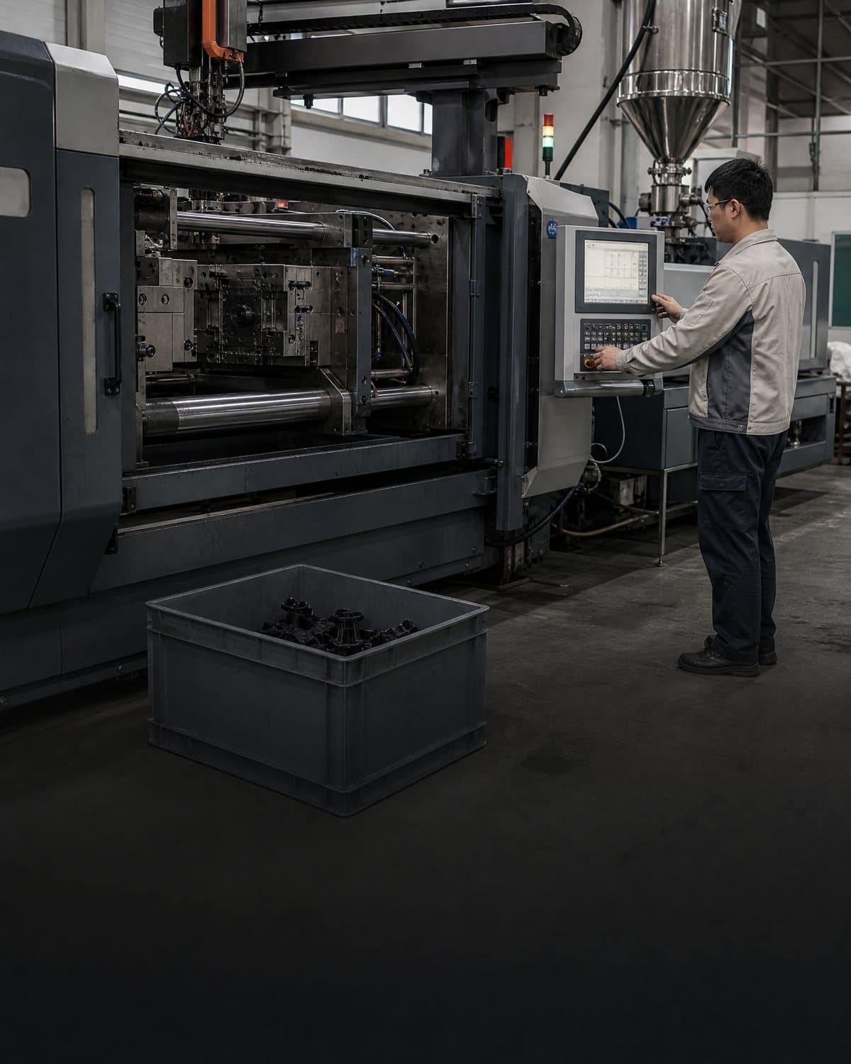
A vertical layout is usually the stronger starting point when a preformed item must sit in a defined location while resin is injected around it. The upward/downward mold motion and open work area can make it practical to load and check terminals, cables, magnets, bushings or other components, manually or by a designed handling system. Vertical insert machines may also use rotary or shuttle tables, allowing one station to be loaded while another is molding.[1][2] This is a process-access advantage, not evidence that any given insert will remain correctly located under injection pressure.
For threaded insert molding, start with the joint requirement rather than the word “threaded.” State the thread designation, fastener direction, expected tightening or service loads, access to the mating component and the intended evidence for torque, pull-out or other relevant behavior. In metal insert molding, identify the functional datum faces, resin keep-out or coverage areas, orientation feature and allowable insert condition. Insert molding commonly places a preformed—often metal—part in the mold before plastic is injected around it; threaded inserts are used to reinforce a plastic part for repeated fastening.[3] The retention geometry, polymer grade and loading method remain part-specific engineering decisions.
02
Choose horizontal when the production flow is the controlling issue
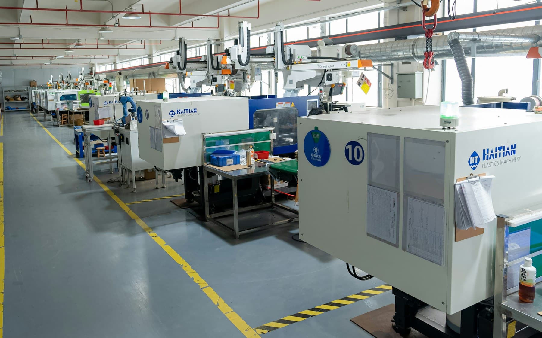
A horizontal layout is often the better starting point for a conventional molded-plastic part that can eject, drop to collection or be removed by a robot without an insert-loading operation at the mold face. It commonly fits cells built around multi-cavity tooling, conveyors, robotic removal, inspection and packing. Machine builders also position horizontal layouts for larger or heavier molds and high-output applications.[1] That does not mean every horizontal cell is faster or lower cost: gate arrangement, cooling, part release, robot path, inspection and packaging can each become the limiting condition.
Use the comparison as a quotation-scoping tool. It separates the reason to investigate an orientation from the proof needed for the actual component. Neither column predicts quality, output, cost or safety for a particular programme. Those outcomes depend on the full mold, resin, handling and controls proposal.
| Decision factor | Vertical starting point | Horizontal starting point | Request |
|---|---|---|---|
| Primary part task | Insert loading, location or checking before molding. | Automatic part removal into downstream handling. | Sequence, locating method and error-proofing. |
| Tool and mold access | Open mold access supports loading or a station concept. | Side-to-side opening suits removal and conveying. | Mold envelope, access and changeover assumptions. |
| Automation focus | Feed, orient and verify inserts; use a shuttle or rotary station if justified. | Remove, inspect, convey or pack parts. | Cell layout and recovery from missing or misoriented components. |
| Demand profile | Specialised part handling remains central as volume develops. | Stable repeat production supports a continuous-flow concept. | Production window, cavitation, handling time and inventory basis. |
03
Size the press around the mold and process, not the machine label
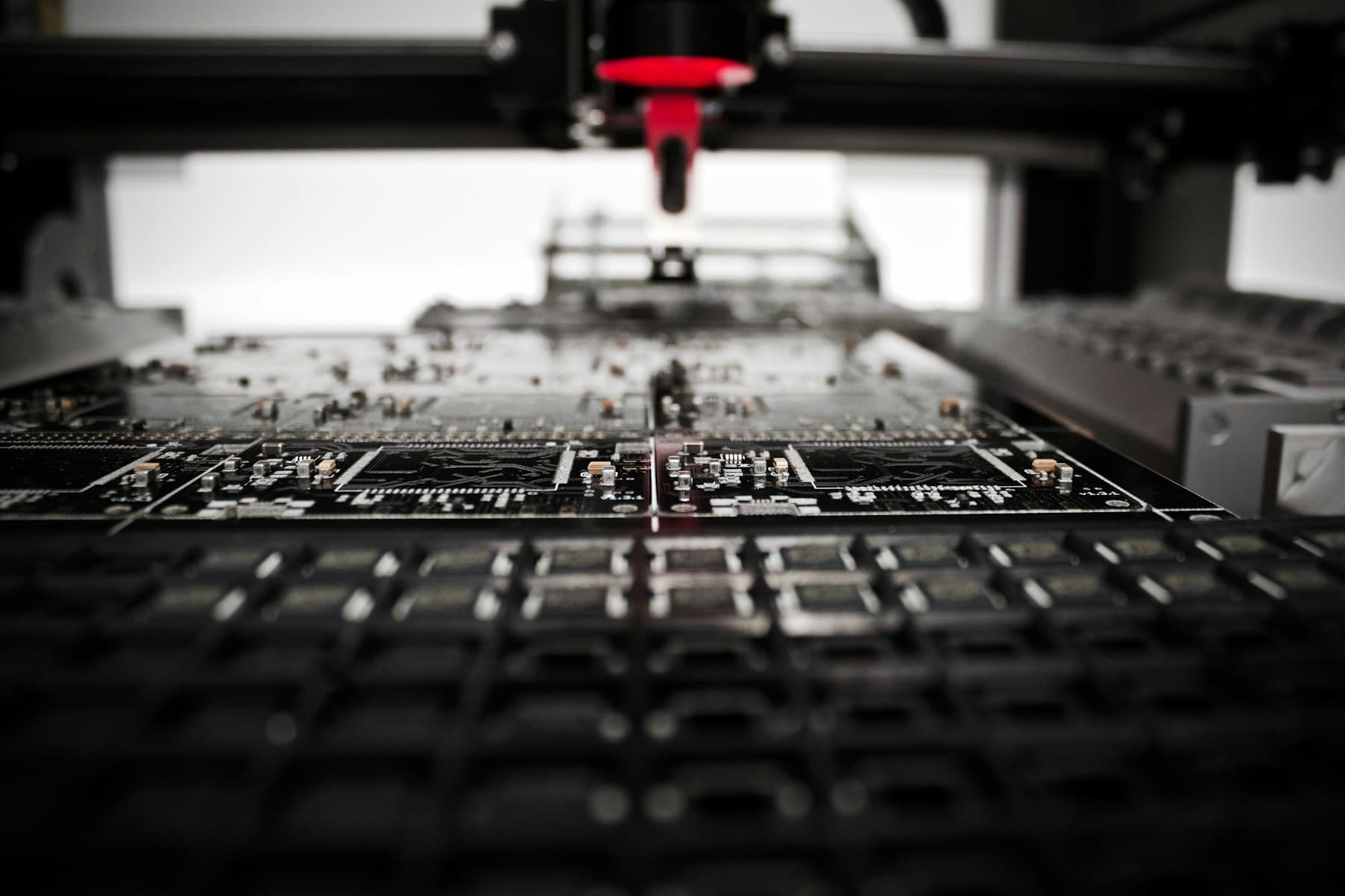
Injection molding press capacity is a package of constraints, not simply a clamping-force number on a quotation. The review should connect projected area and molding pressure assumptions to clamping, then check shot volume, plasticizing capability, tie-bar spacing or platen dimensions, daylight, mold height, ejection, nozzle interface, tool weight and services. A large plastic part does not automatically require a horizontal machine, and a small insert-molded part does not automatically fit a vertical machine. The proposed mold and process establish the usable envelope.
Ask the supplier to show the basis for the proposed press and tool orientation, including the assumed resin grade and cavity arrangement. If an automated cell is proposed, ask how the robot, feeder, guarding, material equipment and maintenance access alter the footprint. ISO 20430:2020 sets safety requirements for the design and construction of injection molding machines and provides information for their safe use; it does not certify a buyer’s product, mold or complete cell.[5] Local legal duties, product requirements and any validation plan must be decided for the specific programme.
04
Treat automation as a handling decision before treating it as a cost line
Automated injection molding is not one feature that makes either orientation preferable. In a vertical cell, the critical question may be whether a feeder can present the correct insert, whether a fixture supports it during mold closing and injection, and how the system detects a missing, wrong or rotated item. In a horizontal cell, the key question may be ejection stability, robot reach, part orientation after removal, cooling before handling, and the hand-off to inspection or packing. Robots are used for insert loading as well as molded-part removal and secondary handling.[4]
For either route, map normal production and exception recovery. Define who may enter the safeguarded area, what happens after a reject or interrupted cycle, how components are segregated, and which signals are recorded for the feature that matters. Do not assume a manual insert operation is unsuitable for a lower-volume programme, or that automation is justified merely because volume is forecast to increase. Compare labor exposure, placement repeatability, fixture complexity, uptime assumptions, changeover and the cost of an escaped placement error against the part’s actual requirement.
05
Put an orientation-specific decision into the RFQ and engineering review
A useful request for quotation states the part revision, material grade direction, annual and batch-demand scenarios, cavity proposal if known, critical dimensions and cosmetic faces. For an insert part, add controlled insert drawings, datum and orientation features, permitted resin coverage, presentation format, mating-part information and the acceptance method. For a non-insert part, add the required part-release and downstream-flow concept. Ask for the proposed orientation, mold arrangement, press-envelope basis, manual or automated handling sequence, open technical assumptions and the evidence proposed at sampling. This lets procurement compare scope rather than comparing an unexplained press choice.
Before a quote or engineering review, make the decision part-specific and record what could change it: a new insert supplier, revised demand, material substitution, added cavity, altered downstream assembly or a higher automation requirement. Select vertical when controlled insert access is the governing problem; select horizontal when stable molded-part flow is governing. Send the controlled CAD, drawing and open questions to info@injeform.com so the quotation discussion can focus on the production route and evidence your component actually needs.
Practical takeaway
Before you move
to the next review.
- Mark on the controlled CAD whether the part needs an insert, where it is located, and every surface that must remain exposed or resin-covered.
- Provide demand scenarios, cavity expectations and the downstream handling or assembly sequence rather than only an annual volume.
- Ask for the proposed mold orientation, press-envelope basis and the assumptions behind clamping, shot, daylight and ejection suitability.
- Request the manual or automated handling sequence, including insert or part orientation, error-proofing and recovery after an interrupted cycle.
- Agree the part-specific sample, inspection and change-control evidence before releasing tooling or committing to cell automation.
FAQ
Common questions
Can a horizontal machine perform insert molding?
Yes. Horizontal machines can mold parts with inserts, but the buyer should ask how each insert is presented, supported and verified before mold closing. If accessible loading and position control are the main risk, a vertical arrangement may be easier to justify. The better choice follows the part, fixture and handling concept—not the process name alone.[1]
Does a vertical machine rule out automated production?
No. Vertical machines can be paired with insert feeders, robots, rotary tables or shuttle tables. The decision is whether that cell can reliably load, locate and verify the actual part within the required production plan. Automation should be reviewed as a complete handling and safeguarding concept, rather than assumed from machine orientation.[2][4]
What is the first question to ask about press selection?
Ask whether the proposed press and mold form a credible package for the part: clamping basis, projected area, shot and plasticizing requirement, mold dimensions, daylight, ejection, services and handling must all be checked together. Any numerical selection and acceptance decision should be based on the final part, material, tooling and process proposal.
References
Source material
- [1] YIZUMI, “Vertical vs Horizontal Injection Molding Machine: Features, Pros, Cons, Applications, and How to Choose.”
- [2] ENGEL, “Vertical Injection Molding Machine Insert.”
- [3] Protolabs, “Design Guidelines: Overmolding & Insert Molding.”
- [4] Yaskawa Motoman, “Injection Molding.”
- [5] International Organization for Standardization, “ISO 20430:2020 Plastics and rubber machines — Injection moulding machines — Safety requirements.”
This guide is general information for early procurement and engineering discussion. It does not replace product-specific DFM, qualification, validation, regulatory assessment or legal advice.