
A sprue bushing is a small part of an injection mold design, but it sits at a high-consequence boundary: hot melt leaves the injection molding machine nozzle and enters the tool under pressure. A familiar nozzle radius or drawing note alone does not establish a reliable seal, alignment or flow path. Wear and prior modification can also change the actual contact condition.
For buyers sourcing injection mold tooling across Europe, the US or the Middle East, the objective is a compatible, inspectable machine–mold interface before trial—not a universal dimension. Identify the intended press or an agreed machine envelope, require the supplier to state the bushing and injection mold nozzle interface, and accept it against defined evidence. This guide does not replace the machine maker’s instructions, the mold maker’s design responsibility or a resin-specific process study.
Treat the sprue bushing and machine nozzle as one mating system. A catalogue radius, a clamp-force number or a successful dry fit by itself does not prove the seal will remain suitable during the agreed trial.
01
Start with a controlled machine-interface sheet, not a press-size assumption
Ask which injection molding machine will be used for first trial and intended production, then request machine-side data from the processor or owner: make and model, injection-unit or nozzle assembly, seat profile and radius, nozzle orifice, reach, locating-ring/platen interface, and any tip or extension. State units and source revision. A 0.5 in or 0.75 in label is shorthand, not a substitute for a controlled drawing or measured feature.
Do not use injection molding machine tonnage as a proxy for nozzle compatibility. Clamp force may affect mold selection, and injection-unit contact force may matter to a seal, but neither defines the seat radius, tip opening, centerline or usable travel. If the final production machine is unknown, set a written machine-interface envelope and flag dimensions for reconfirmation before shipment.
The mold-side record should show the injection mold sprue bushing part number or controlled detail, seat geometry, inlet orifice, installed length and locating-ring relationship. Catalogues show multiple radius, orifice, length and mounting options; a generic component name does not establish interchangeability.[2] For a custom bushing, request the released drawing and inspection basis.
| Input to freeze | Why a buyer needs it | Supplier or processor confirmation | Risk if assumed |
|---|---|---|---|
| Actual press and injection unit | Links the tool to the nozzle assembly that will contact it | Machine ID, nozzle/tip configuration and intended trial press | The tool fits a different machine than the one used at trial |
| Seat profile and radius | Defines the intended metal-to-metal contact geometry | Controlled nozzle and bushing dimensions, units and drawing revision | A matching label masks a poor or asymmetric seal |
| Nozzle and bushing orifices | Sets the transition into the sprue and affects flow restriction | Intended relationship, resin basis and any special nozzle tip | Unexplained pressure loss, hang-up or a nonrepresentative trial |
| Locating and centerline arrangement | Helps keep the nozzle on the designed bushing axis | Locating-ring interface, platen fit, projection and clearance | Side loading, leakage or damage at setup |

02
Specify contact geometry and flow opening as separate decisions
The spherical seat and the melt passage solve different problems. First, the injection mold nozzle tip and the bushing seat need the intended contact pattern to seal without excessive contact area or a one-sided high spot. Plastics Technology documents leakage, air entry, altered heat transfer and safety exposure as possible consequences when nominally matching tips and bushings do not actually mate well.[1] The buyer’s requirement should therefore be an agreed mating geometry and verification method—not merely a statement that both items are ‘the same radius.’
Second, select the nozzle orifice and sprue-bushing inlet with the resin, shot, expected pressure, nozzle style and runner concept in view. An overly restrictive opening can raise pressure demand or create shear and residence-time concerns; an unsuitable transition can complicate start-up, stringing or cold-slug control. The processor and toolmaker should confirm the intended orifice relationship and its calculation, simulation or prior-process basis—especially for filled, heat-sensitive or high-temperature materials.
Record whether the tool uses a conventional cold sprue, an extension arrangement, a heated sprue bushing or a hot-runner interface. A hot-runner system introduces its own nozzle, manifold, thermal-control and service requirements. Ask who owns the interface definition and require one resolved drawing before manufacture or modification.
03
Check alignment, reach and load path before the mold ships
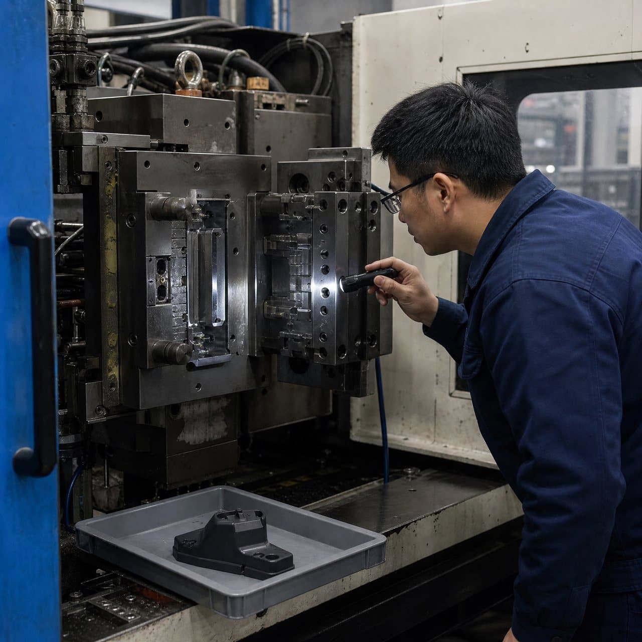
A correct radius will not compensate for a nozzle that cannot reach the designed seat, a locating ring that does not locate as intended, or an injection unit that approaches off centre. Review the assembly drawing against the intended machine: locating-ring outside diameter and projection, platen opening, nozzle clearance, bushing position, nozzle travel and any adapter or insulation plate. This is a machine-fit review within the injection mold design package.
Ask the supplier to identify the datum scheme relating the bushing seat, locating-ring feature and mold mounting faces. For an adapter, extension nozzle or nonstandard locating ring, obtain its drawing, fastening and service responsibility. A temporary shop adapter may suit a defined trial, but declare it; do not treat it silently as the production configuration.
A mold may be within the requested injection molding machine tonnage range and still have an unresolved nozzle interface. Nor does a low-pressure dry contact establish performance at trial temperature, contact force and injection pressure. Require the processor to confirm the setup window and safety procedure; do not infer machine limits from a nameplate.
04
Accept the interface on traceable evidence, then retain a change trigger
Before T0 or the agreed first trial, require an interface package proportionate to risk: actual or approved machine envelope; mold and bushing revision; nozzle or tip part number; dimensioned interface drawing; critical-feature inspection record; and planned resin and trial conditions. If physical mating is available, agree how contact will be checked. Pressure-sensitive film or a controlled transfer method can reveal contact distribution.[1] That result applies to the tested setup, not every press or nozzle tip.
During trial, retain the machine setup reference, nozzle temperature setting, resin identification, start-up observations and any leak, stringing, cold-slug, splay or pressure concern. Inspect the bushing and tip after symptoms, unplanned adjustments or a new interface component. Treat a leak as a safety and process issue; stop and follow the site’s machine-safety procedure rather than attempting an informal correction near hot equipment.
Close with a disposition: accepted for the named press and configuration; accepted with production-machine confirmation outstanding; or not accepted pending correction and repeat evidence. Set change triggers for a different press, tip, injection unit, bushing, adapter, hot-runner configuration or resin/process window. Where the decision is tolerance-sensitive, request a suitable measurement-method confirmation; NIST notes that gauge R&R evaluates measurement repeatability, reproducibility and stability.[3]
Practical takeaway
Before you move
to the next review.
- Name the intended trial press or issue a controlled machine-interface envelope before releasing the bushing detail.
- Obtain machine-side nozzle-seat, tip/orifice, reach, locating and centerline information in stated units and revisions.
- Require the supplier to confirm the bushing seat geometry, inlet, installed length, datum relationship and runner or hot-runner configuration.
- Approve contact and flow decisions separately; do not equate nominal radius, press tonnage or a dry fit with a production-ready seal.
- Retain drawing, inspection and trial evidence, and repeat the confirmation when the machine, nozzle, bushing, adapter or material/process basis changes.
FAQ
Common questions
Must the nozzle-tip radius exactly equal the sprue-bushing radius?
Do not assume an exact numerical equality is the correct requirement across all component designs. Obtain the nozzle and bushing drawings, confirm the intended mating geometry with the responsible supplier and processor, and verify the actual contact pattern on the agreed machine configuration.
Can a mold be approved when the production machine has not been selected?
It can be conditionally released against a documented machine-interface envelope, provided the outstanding dimensions and responsible confirmer are clear. Before shipment or production approval, reconcile the actual machine nozzle, locating arrangement, reach and any adapter with the released mold detail.
What evidence should accompany a nozzle-to-sprue compatibility claim?
Ask for controlled machine and mold interface drawings, component identifiers, critical-dimension inspection evidence, a declared trial setup and a documented contact or trial result. Add a clear change-control trigger for a new press, tip, bushing or hot-runner configuration.
References
Source material
- [1] Plastics Technology, “The Trouble With Mismatched Nozzle Tips & Sprue Bushings.”
- [2] MISUMI, “Guide for Sprue Bushings and Locating Rings.”
- [3] National Institute of Standards and Technology, “Gauge R & R Studies.”
This guide is general information for early procurement and engineering discussion. It does not replace product-specific DFM, qualification, validation, regulatory assessment or legal advice.