
Choosing large part injection molding changes the decision from selecting a resin and a nominal press to managing a larger, connected system. The part’s footprint, mass distribution, cosmetic faces, functional datums and route after ejection all become more consequential. An OEM should therefore treat the initial concept as a part-specific manufacturability and cell-planning review, not as a request for a bigger machine. Available clamp force must resist pressure acting across the total projected area at the parting line, including a cold runner where one is used.[1]
The practical change is that a local compromise can affect the whole part. A gate location can change flow and orientation; a wall transition can change cooling and shrinkage; a support point can change how a warm part settles after ejection. In a quote or engineering review, injection molding press capacity and injection molding machine tonnage should be considered alongside the tool interface, shot and recovery needs, cooling, ejection and controlled handling—not as standalone ratings.
Clamp-force planning starts with the mold’s total projected area and a part-specific pressure basis; it is not a generic machine-size shortcut.[1]
01
Reframe the brief around the complete part envelope
For a large molded component, the drawing envelope is only the first input. The buyer should identify the projected area at the parting line, broad unsupported panels, deep features, nominal and local wall changes, datum scheme, visible faces and the direction in which the part will leave the tool. These inputs affect the mold architecture and how the part is supported while it is still releasing heat. A broad, shallow cover and a similarly sized structural tray can create very different planning questions even if both fit inside the same nominal machine window.
This is where early commercial comparisons often become unreliable. One proposal may assume one cavity, a different gate strategy or simple drop handling; another may include support, fixtures or downstream checks. Neither should be treated as equivalent until the part revision, resin direction, cosmetic boundary, cavitation, runner concept and acceptance criteria are aligned. The goal is not to eliminate iteration; it is to expose the assumptions that determine whether a quoted concept is technically comparable.
02
Make the mold concept carry the larger risk deliberately
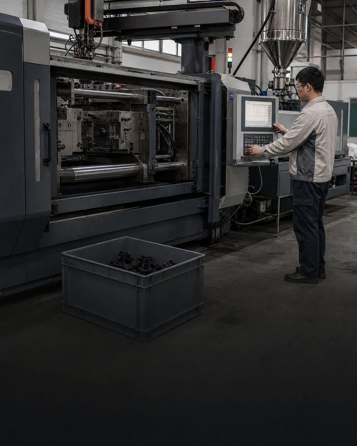
Injection mold tooling for a large part is a system of cavity and core steel, runner and gate layout, cooling, venting, ejection and any needed actions—not merely a larger negative of the CAD shape. Gate position and number influence flow path, pressure, weld-line location, orientation and gate witness. Cooling and ejection must be planned in relation to the geometry, not added as late accessories. Eastman’s processing and mold-design guidance identifies cooling, gate design, venting and ejection as linked mold-design decisions.[3]
Before design release, ask how the supplier proposes to protect the function that matters most: flatness at a seal, position of mounting features, appearance of a broad face, or fit to a mating part. The following compact comparison helps keep the conversation decision-specific. It does not prescribe a universal configuration; the suitable choice remains dependent on the exact geometry, resin grade, finish and volume case.
| Decision point | Simpler assumption | Large-part review question |
|---|---|---|
| Cavitation and runner | Select by annual volume alone. | What projected area, shot, flow balance and part removal burden does each concept create? |
| Gate strategy | Place a gate where it is least visible. | How will gate location affect fill path, weld lines, orientation, pack transmission and the cosmetic boundary? |
| Cooling | Add circuits after the cavity shape is set. | Which regions need balanced thermal control, and how will core, cavity and local features be addressed? |
| Ejection and support | Eject into an open bin or conveyor. | Where may a warm part be contacted, supported, oriented and separated without marking or distorting it? |
| Acceptance | Use general dimensions at room temperature. | Which datums, conditioning state, cosmetic zones and assembled functions define an acceptable part? |
03
Treat warpage as a cross-functional acceptance risk
Injection molding warpage is not a single-cause issue that can be answered from overall part size. Autodesk separates contributors to shrinkage-related deflection into differential cooling, differential shrinkage and orientation effects; orientation can reflect molecular or fibre alignment.[2] That is why a buyer should avoid asking only whether a part will be “flat.” Ask which datum, direction and assembled condition matter, and whether the concern is a modeled prediction, an early sample observation or an agreed acceptance measurement.
The review should connect geometry, resin direction, gate concept, thermal design, process approach and post-ejection handling. For example, material-maker guidance for one engineering resin advises checking gate locations and number of gates to reduce orientation, equalising wall variation, balancing cooling and reviewing handling after ejection when investigating distortion.[4] Those are useful planning prompts, not transferable prescriptions for every polymer. Simulation, sampling, measurement method and any support fixture should be agreed against the actual part and intended use.

04
Size the press and downstream cell as one operating envelope
A larger machine is not automatically the answer. Clamp force is the force available to hold the mold closed against cavity and runner pressure, and it should be calculated for the particular mold rather than set at the machine maximum.[1] The machine review also needs the usable shot range, plasticising and recovery behaviour for the chosen resin, injection-rate requirements, platen and tie-bar fit, mold-height range, opening stroke, ejector interface, nozzle arrangement and utility connections. A favorable tonnage figure does not by itself demonstrate compatibility.
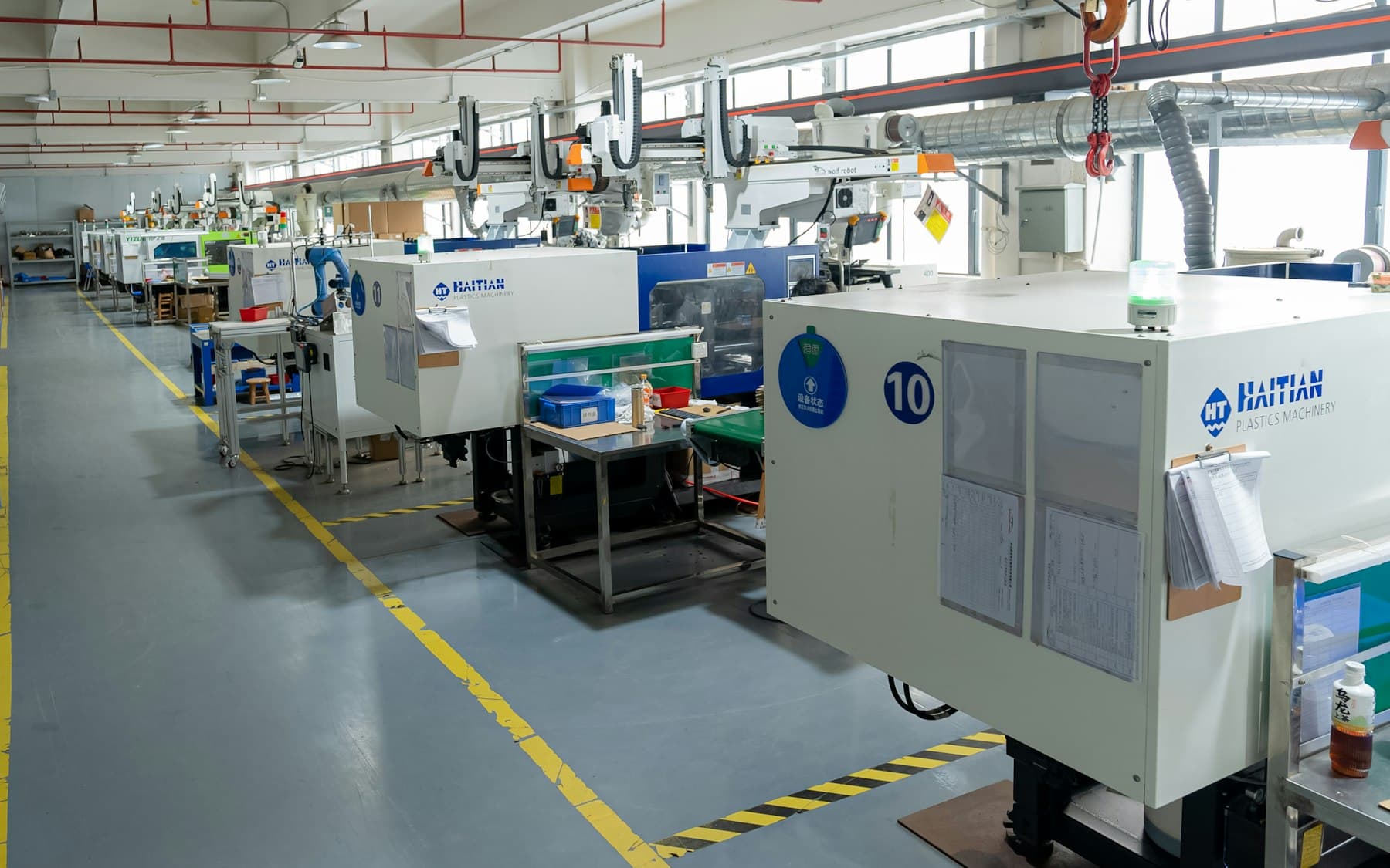
The cell boundary also expands. Define where the part is picked up, its contact points, orientation, protection of cosmetic surfaces, cooling or staging condition, inspection handoff and reject route. Large parts can be awkward to remove consistently even when the cavity fills; the product’s own stiffness while warm, gripper access and the amount of clear mold-open space are part-specific questions. State whether a proposed takeout, fixture or inspection step is an assumption, a concept to be developed, or evidence from the agreed part revision.
05
Convert the engineering review into a quote-ready decision record
A useful request for quotation makes trade-offs visible. Give every bidder the controlled CAD revision, available 2D drawings, resin or allowed alternatives, forecast by phase, annual mix where relevant, cosmetic zones, critical functions, assembly interfaces, pack-out route and target evidence stage. Ask each proposal to distinguish a preliminary recommendation from a configuration that has been reviewed against final geometry. If a requirement concerns food contact, medical use, flame behaviour, chemicals, safety or another regulated application, it requires a separate product-specific regulatory and validation decision; this general planning guide is not evidence of compliance or performance.
Before requesting a quote or engineering review, align the large-part brief, acceptance plan and commercial assumptions. Invite the supplier to identify the unknowns that could change the tool or cell concept, then resolve them before treating price or timing as a commitment. Send the package to InjeForm at info@injeform.com with the drawing revision and the decisions still open; that gives the review a practical basis without assuming a factory capability or outcome.
Practical takeaway
Before you move
to the next review.
- Identify the controlled CAD revision, parting-line projected area, critical datums, cosmetic faces and assembly functions.
- Request a part-specific explanation of clamp force, shot and recovery, mold-to-press fit, opening stroke and utility assumptions.
- Compare gate, runner, cooling, venting and ejection concepts against the same resin direction and cavitation basis.
- Define how the warm part will be supported, transferred, inspected, staged and packed after ejection.
- Separate preliminary estimates from evidence needed for the actual part, including measurement, validation and any regulatory review.
FAQ
Common questions
Does a larger part always require a higher-tonnage machine?
Not automatically. The required clamp force depends on the particular mold’s total projected area and pressure conditions, while machine suitability also depends on shot, injection unit, physical mold fit, stroke, utilities and the downstream cell. Use tonnage as one review input rather than a size label.[1]
Can a mold-flow or warp analysis replace physical sampling?
No. Analysis can help the team investigate contributors and compare concepts before tooling or trials, but it is a model built from inputs and assumptions. The agreed part geometry, resin grade, process, measurement method and acceptance condition still need part-specific confirmation. Autodesk notes that its warp results combine several modeled effects, including differential cooling, differential shrinkage and orientation.[2]
What should an OEM give a supplier before requesting a large-part quote?
Provide the controlled CAD and drawing revision, intended resin direction, forecast and mix, cosmetic and functional requirements, critical datums, assembly interfaces, pack-out expectations and the stage of evidence required. Also state what remains undecided, such as gate visibility, handling approach or validation plan, so quotes can label assumptions rather than hide them.
References
Source material
- [1] RJG, “Clamp Force: Why It’s Vital to Your Injection Molding Process and How to Calculate It.”
- [2] Autodesk Support, “How to Interpret Deflection Results in a Moldflow Warp Analysis.”
- [3] Eastman, “Processing and Mold Design Guidelines.”
- [4] SABIC, “ULTEM™ Resin Processing: An Introduction and Troubleshooting Guide.”
This guide is general information for early procurement and engineering discussion. It does not replace product-specific DFM, qualification, validation, regulatory assessment or legal advice.