
Injection-molded threads and screw bosses can reduce assembly count and support repeatable fastening, but they are not interchangeable features. A molded thread may provide a direct mating interface, while a boss usually provides wall thickness, alignment and material around a self-tapping screw, machine screw or post-installed fastener. For an overseas OEM buyer, the right choice depends on the screw system, resin and reinforcement, boss geometry, tool release strategy, assembly torque, service environment and inspection method. Treat the feature as part of a joint design—not as an isolated CAD detail—and require evidence at each approval gate.
There is no universal molded-thread size, boss wall, torque value or pull-out strength. Set requirements from the actual fastener, resin grade, geometry, load case, environment and validated assembly test.
01
Choose the fastening concept before choosing the feature
Start with the joint function. A direct molded thread may suit a reusable closure or low-load cover when the resin, thread form, engagement length and assembly method are controlled. A screw boss may be better when the fastener cuts or forms its own thread, when a machine screw is installed into a separate feature, or when the boss must also locate a mating component. If the joint needs frequent service, high clamp load, controlled torque retention or resistance to heat and chemicals, compare a molded feature with a post-installed threaded insert or another fastening architecture rather than assuming plastic threads are the lowest-risk option.
Define the load direction and failure mode in the drawing or RFQ: stripping, boss cracking, pull-out, head pull-through, creep, loosening, thread cross-start, assembly damage or loss of clamp load. State whether the screw is driven once, removed repeatedly, or installed by an automated tool. A supplier should be able to explain the proposed thread or boss against these conditions and identify which values are requirements, which are design targets and which remain to be proven by testing.
A molded-in feature can be attractive for part-count and assembly reasons, but it may increase tool complexity, draft or ejection considerations. Internal threads can require an unscrewing mechanism, collapsible core, split core or a geometry-specific alternative; the suitable approach depends on thread form, pitch, depth, parting strategy, resin and production volume. Ask for a tool concept before treating a thread callout as a simple add-on.
02
Compare molded threads, screw bosses and inserts on the same decision basis
The table below is a sourcing comparison, not a universal ranking. The supplier should confirm the feasible option after reviewing the controlled CAD, fastener drawing, resin grade, assembly equipment and expected demand. Published design guidance can identify common risks, but it cannot replace a part-specific torque, retention or life test.
For procurement, request separate pricing and schedule assumptions for materially different concepts. A molded thread may avoid a secondary insert operation but require more complex tooling. A boss for a self-tapping screw may simplify the mold but move risk into screw selection, pilot geometry and automated assembly. An insert can improve thread durability in some applications but adds component sourcing, loading, location and traceability requirements. Compare total process risk, not only the nominal part price.
| Option | Potential fit | Buyer must verify | Typical approval evidence |
|---|---|---|---|
| Direct molded internal or external thread | Reusable closure, cap, or plastic-to-plastic interface where load and wear are bounded | Thread form, draft or release method, pitch, engagement, flash, start alignment and resin durability | Thread gauge or mating-part fit, dimensional report, assembly torque and repeated-cycle test when reuse is required |
| Boss for self-tapping or thread-forming screw | Enclosures and brackets using a defined screw and controlled installation process | Pilot diameter, wall and base support, screw compatibility, torque window, cracking and stripping risk | Boss dimensions, screw installation study, torque-to-failure or pull-out data, visual crack check and cavity traceability |
| Boss for machine screw with post-installed thread | Applications needing a standard metal thread without molding the thread directly | Insert or nut retention, concentricity, seating, exposed metal, loading method and corrosion compatibility | Insert or nut location, thread gauge, retention test, flash/bleed inspection and supplied-component traceability |
| Post-mold heat-staked, ultrasonic or press-installed insert | Higher serviceability or repeated assembly where the joint justifies a secondary operation | Insert material and finish, equipment settings, part support, cycle effect and operator or automation controls | Process window, pull-out or torque test, insert position, cosmetic criteria and change-control record |
03
Design the boss around the fastener, resin and load path
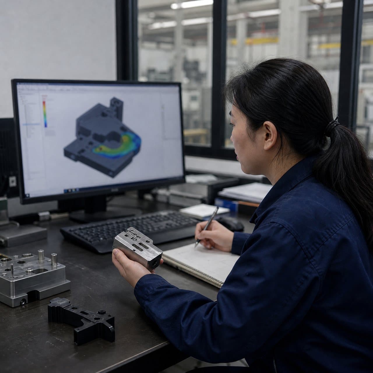
A screw boss should be reviewed as a load path from screw head and thread engagement through the boss wall, base and surrounding housing. Avoid treating nominal outer diameter or wall thickness as portable rules. The suitable proportions depend on screw diameter, thread-forming profile, insertion torque, resin shrinkage, filler orientation, local wall thickness, nearby ribs, draft, cooling and the required safety factor. Ask the molder to mark the proposed boss, base radius, draft, support ribs and steel conditions in a DFM review.
Provide the exact approved resin grade, color or additive state, reinforcement, moisture condition and expected service environment. Unfilled and glass- or mineral-filled grades can behave differently in shrinkage, stiffness, brittleness, creep and tool wear. Temperature, humidity, chemical exposure, vibration and sustained clamp load can change the joint outcome. A resin-family name alone is not enough to approve a torque or retention claim.
Use ribs or gussets when they improve the load path, but check sink, weld lines, filling, ejection and access for the driver. Keep the screw axis controlled from a defined datum and identify nearby features that can distort the boss or obstruct the tool. If a boss is also a locating feature, seal support or cosmetic surface, separate those functions into CTQs so a pass on one dimension does not hide a failure in another.
Do not ask a supplier to promise a universal life, cycle count or torque window before the joint is tested. Instead, define the screw, driver bit, speed, seating method, torque limits, installation count, conditioning state and acceptance criteria. The resulting window should be tied to the approved part, machine and process—not copied from a different resin or screw.
04
Control molded threads and bosses through tooling and process review
At tool review, request a feature map showing the thread or boss axis, parting line, shutoffs, core or unscrewing mechanism, vents, gates, ejectors, cooling and access for maintenance. Internal thread quality can be affected by core alignment, release, polymer drag, flash and local packing. Boss quality can be affected by core-pin support, gas traps, knit lines, uneven cooling and ejection loads. The tool concept should explain how the critical feature will be formed, released, inspected and repaired.
Ask the supplier to identify steel-safe dimensions and which adjustments are possible after first trial. A feature that is easy to measure may not be easy to correct without changing engagement, wall support or the mating datum. For multi-cavity tools, require cavity identification and a plan to compare thread fit, boss location, flash and functional test results cavity by cavity. Tooling changes, resin changes, repaired cores and process relocation should trigger a documented review of affected CTQs.
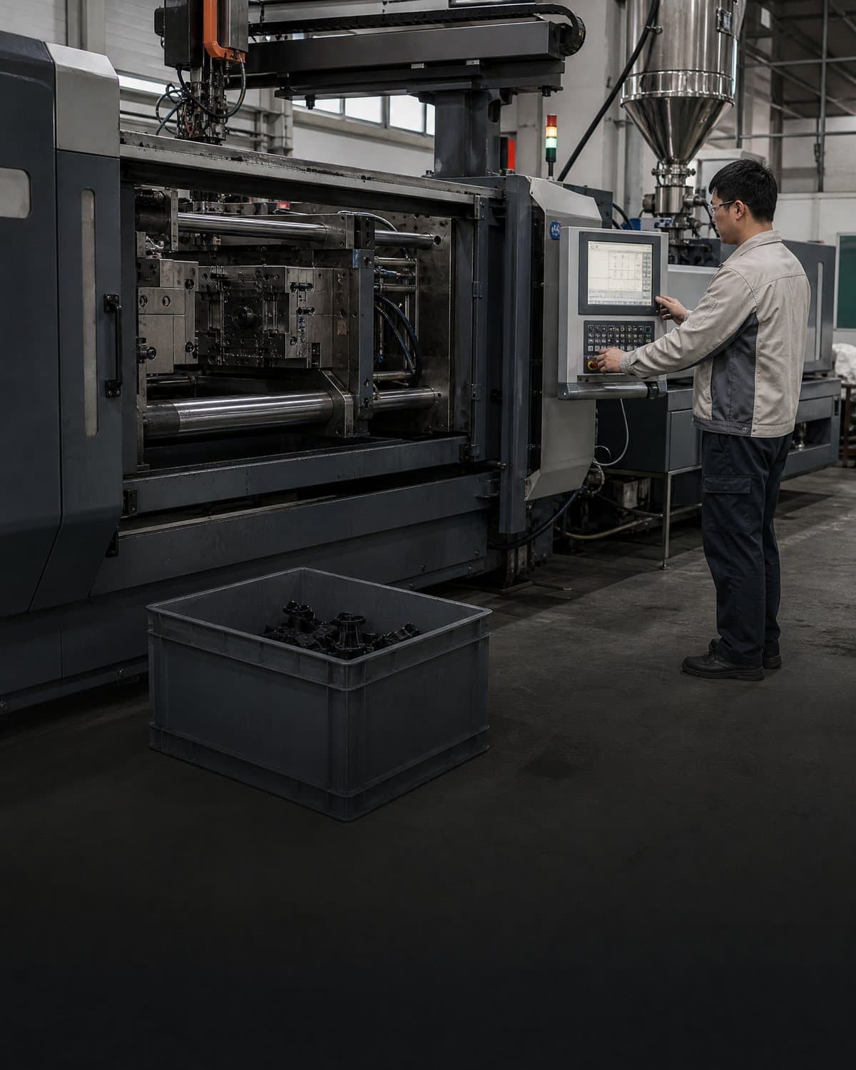
Process controls should cover resin drying or conditioning where applicable, melt and mold-temperature ranges, fill and pack settings, cooling, ejection and handling. Do not approve a cycle-time or capacity statement as a quality guarantee; those outcomes depend on the actual tool, machine, cavity count, resin, validated process window, inspection and demand profile. Require trial records that connect settings and material lots to measured and functional results.
For overseas sourcing, evidence should be shareable without relying on a verbal factory update. Request dated DFM comments, controlled drawings, tool revision, sample identification, material certificates or lot records as applicable, dimensional results, functional-test method, deviations, corrective actions and the next approval gate. This creates an auditable basis for procurement and quality teams working across time zones.
05
Set acceptance criteria and approval gates for the released joint
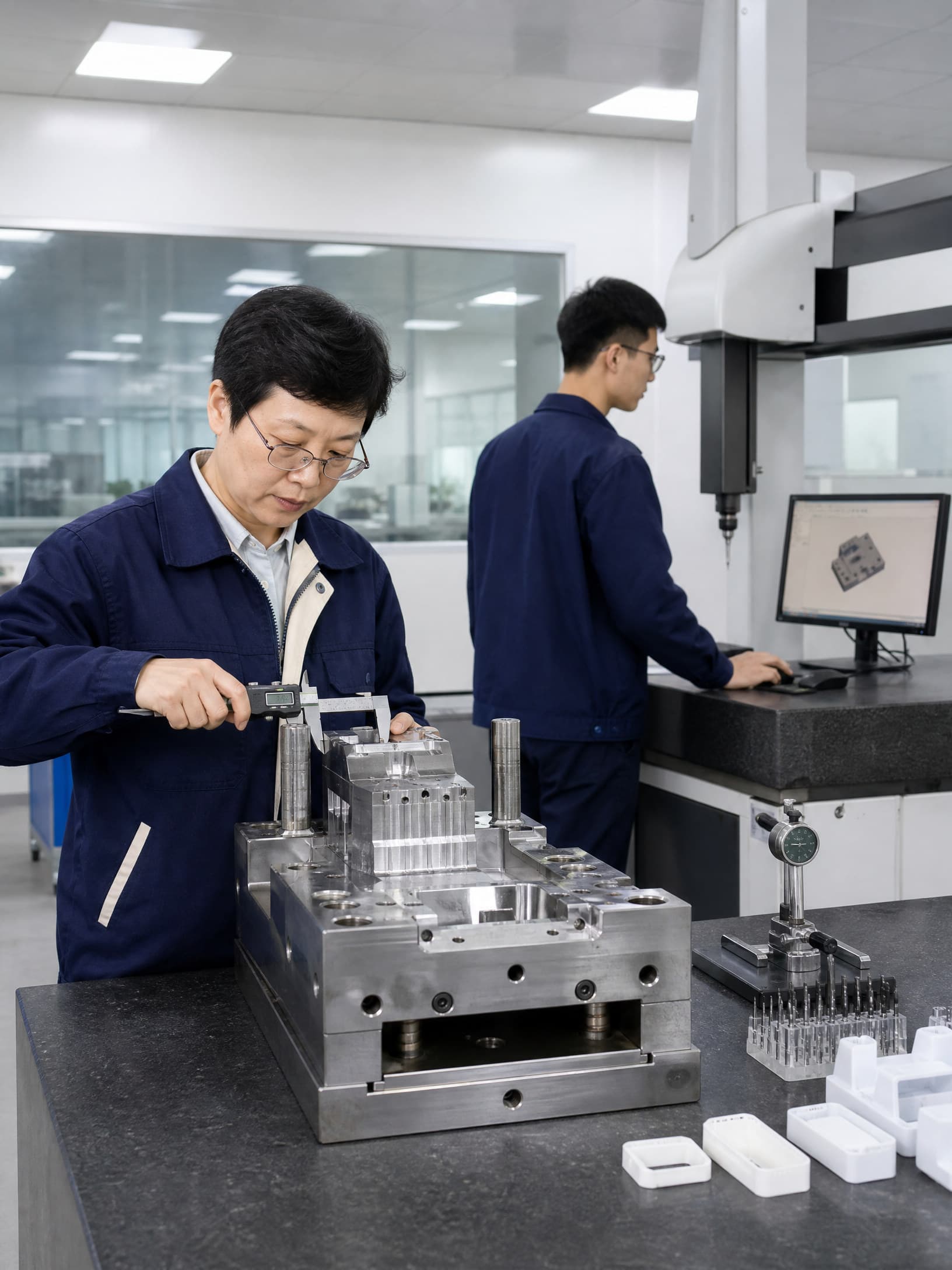
Separate appearance, dimensional and functional requirements. A thread may look acceptable but fail a mating gauge; a boss may meet an outside diameter but crack during screw installation. Define the datum scheme, measurement condition, sample quantity, cavity identity, gauge or mating hardware, conditioning interval and acceptance limit. If a standard such as a thread specification is used, state the applicable standard and class rather than writing only nominal diameter and pitch.
Use a staged approval route. At design review, approve the joint concept, fastener, resin direction, CTQs and test plan. At tool review, approve the forming and release strategy, support, venting, ejection, repair access and inspection method. At T1 or equivalent trial, review dimensional and visual evidence plus assembly torque, seating, retention or repeated-use results as applicable. Before production release, confirm the approved sample, process range, cavity results, packaging and change-control rules.
Supplier evidence should answer practical buyer questions: Which cavity made the sample? Which resin and lot were used? Was the sample conditioned? What screw, driver and fixture were used? Were torque values measured at seating, stripping or failure? Were cracks, flash, blocked threads and boss distortion checked under magnification where appropriate? If a result is outside the requirement, record the deviation and disposition instead of silently accepting a different limit.
The final purchase specification should identify the controlled part revision, fastener source or permitted equivalents, resin grade, joint test method, visual limits, sampling plan, packaging protection and notification path for changes. Revalidate the affected evidence after a material substitution, screw change, mold repair, core or insert change, process relocation, cavity addition or assembly-equipment change.
Practical takeaway
Before you move
to the next review.
- Define the joint load cases, screw type, installation method, reuse expectation, environment and failure modes before selecting a molded thread or boss.
- Provide the controlled resin grade, reinforcement, color or additive state, fastener drawing, mating parts, datums and CTQs in the RFQ.
- Request a DFM and tool concept covering thread or boss formation, release, draft, support, venting, gates, ejection, cooling and maintenance access.
- Require cavity-identified samples and evidence for dimensions, thread fit, flash, cracks, installation torque, retention or repeated-use performance as applicable.
- Set approval gates and change control for resin, fastener, tooling, core condition, process location, inspection method and assembly equipment.
FAQ
Common questions
Are molded plastic threads better than screw bosses for OEM parts?
Neither is universally better. A direct molded thread can suit a defined reusable interface, while a screw boss can suit a specified self-tapping or machine-screw joint. Compare service load, reuse, resin, tooling, assembly equipment, environment and validated functional evidence before selecting the feature.
How much wall thickness should an injection molded screw boss have?
There is no responsible universal value. The requirement depends on screw geometry, resin grade and reinforcement, boss diameter, base support, nearby walls, shrinkage, installation torque, temperature, sustained load and the required safety margin. Ask the supplier to propose geometry after reviewing the complete joint and prove it with assembly or retention testing.
Can an injection molder guarantee screw-boss pull-out strength or torque?
A supplier can commit to an agreed acceptance result when the part, fastener, resin, process, conditioning and test method are controlled. A generic guarantee is not meaningful because pull-out and torque vary with geometry, material, screw, fixture, installation settings and environment. Put the test method and limit in the drawing or quality agreement.
What should buyers request before approving molded threaded parts?
Request the controlled DFM and tool concept, resin and fastener identification, CTQ and datum map, cavity-identified samples, dimensional and visual results, thread-gauge or mating-fit evidence, defined torque or retention testing, deviations, corrective actions and change-control commitments. Approve the joint only after the evidence matches the intended assembly and service conditions.
References
Source material
- [1] Protolabs, Overmolding and Insert Molding Design Guidelines
- [2] SPIROL, Inserts for Plastics Design Guide
- [3] BASF, Injection Molding: Troubleshooting Guide
- [4] Autodesk, Injection Molding Design and Analysis Resources
This guide is general information for early procurement and engineering discussion. It does not replace product-specific DFM, qualification, validation, regulatory assessment or legal advice.