
Injection molded plastic hinges can reduce part count and assembly work, but the right hinge architecture depends on what the product must carry, how it moves and how it will be validated. A living hinge flexes in a thin section of the molded polymer. A mechanical plastic hinge uses separate knuckles, a pin or another retained feature. These are not interchangeable solutions: a living hinge may suit a light, integrated flap, while a pinned hinge may be more appropriate for controlled rotation, higher load, replaceable hardware or a defined friction torque.
For an overseas OEM buyer, the sourcing decision should start with the requirement rather than a generic promise of cycle life. Define motion, load, angle, environment, mating parts, appearance, material restrictions, forecast and approval tests. Resin grade, additives, flow orientation, hinge geometry, gate and vent layout, tool steel, molding machine, process window, conditioning, volume and customer specifications all influence the result. Treat supplier guidelines as design inputs and require evidence on production-intent samples before approving the tool or finished part.
Do not approve a living hinge from a thickness rule or a claimed cycle count alone. Freeze the exact resin grade, geometry, flow direction, flexing condition and acceptance test, then review tool and sample evidence against the application.
01
1. Choose a living hinge or a mechanical plastic hinge by function
A living hinge is a deliberately thin flexible web molded as part of the surrounding component. It can be useful for caps, lids, covers, dispensing closures, clamshells and compact enclosures where the hinge is integrated, the movement is relatively simple and the product can tolerate a material-defined flex zone. Polypropylene and some polyethylene grades are common starting points because their toughness and ductility can support repeated flexing, but a polymer family name is not a finished specification. Exact grade, melt-flow behaviour, additives, colour, fillers, temperature and chemical exposure still need review.
A mechanical plastic hinge uses a pin, knuckles, barrels, interlocking ears or another articulated feature. It may be the better route when the assembly needs higher load capacity, a controlled rotational torque, a removable door, a stop, a replaceable pin or a different material at the hinge interface. It adds parts, clearances, assembly and wear questions. Those trade-offs may be justified when the hinge is a structural or service-critical joint rather than a compliant flap.
Separate requirements from recommendations in the RFQ. Requirements should state the permitted motion, load direction, open and closed positions, minimum clearance, retention, appearance, environment, assembly condition and test method. Recommendations may cover a candidate resin, hinge type, gate location or initial thickness. Ask the supplier to explain each recommendation and identify what remains unproven rather than treating a standard design rule as universal.
| Hinge route | Potential fit | Main risk to review | Evidence before approval |
|---|---|---|---|
| Integrated living hinge | Low-part-count lids, caps, covers and light-duty repeated flexing | Fatigue, stress concentration, flow orientation, environmental embrittlement or excessive operating force | Named-grade samples, hinge geometry review, flex-cycle protocol and conditioned functional testing |
| Pinned or knuckle plastic hinge | Defined rotation, higher load, replaceable hardware or a required stop | Pin retention, knuckle wear, clearance stack, friction change, flash or assembly damage | Torque/load test, dimensional inspection, assembly study and wear or cycle evidence as required |
| Hybrid plastic hinge with metal pin | Plastic housing with a separate load-bearing or wear-resistant pivot | Insert placement, corrosion or compatibility, overmolding distortion and secondary assembly | Insert specification, retention test, cross-section, assembly validation and environmental review |
| Separate polymer hinge component | A replaceable hinge or material combination that cannot be molded as one piece | Extra parts, tolerance stack, supplier interfaces and assembly cost or variation | Interface drawing, mating-part study, assembly work instruction and finished-product testing |
02
2. Design the living-hinge geometry around strain and flow
A living hinge works by concentrating bending in a thin web while the adjoining sections remain comparatively rigid. The web must not be treated as an arbitrary thin wall. Thickness, width, transition shape, recess or shoulder, bend angle, adjoining wall height and support conditions change the strain and operating force. Published starting points often place molded living-hinge thickness in a small fraction-of-a-millimetre range, but the correct value depends on the selected material, tool capability, part size, flex requirement and customer specification. Use a steel-safe approach where practical: start from a reviewed design and allow controlled tool adjustment rather than assuming one dimension will work for every resin.
Use generous, continuous radii at the transitions into the flexible web to reduce abrupt stress concentration and help the melt enter the feature. A recessed flat or shoulder can help the hinge bend where intended and provide closing clearance, but it also changes filling, ejection and the space available in the closed assembly. Avoid sharp corners, sudden thickness steps, unsupported long spans and cosmetic features that interrupt the hinge unless their effect is specifically reviewed.
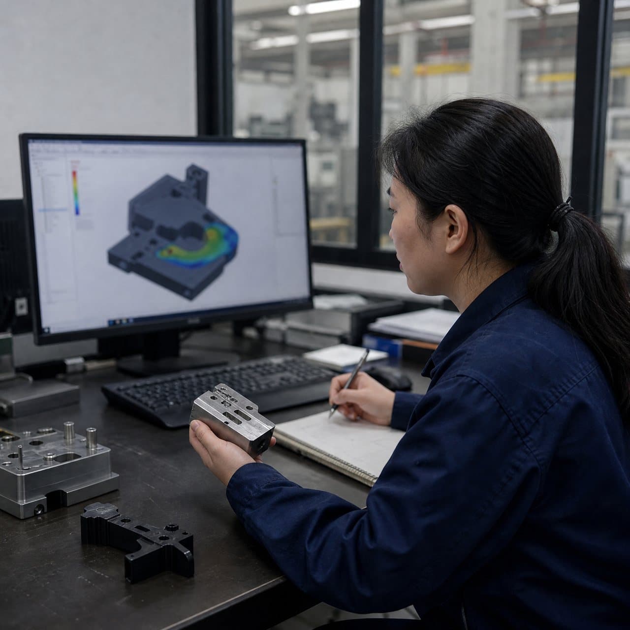
Gate placement and flow direction deserve an early design decision. The supplier should show how the melt will travel through the hinge, where weld or knit lines could occur, how the cavity will vent and whether the part will be molded open, closed or at an intermediate angle. Flow orientation can influence flex performance and dimensional movement. A simulation can identify risks, but only production-intent parts made from the proposed grade and tool concept can support the final approval.
03
3. Select resin and define the service environment at grade level
Polypropylene is a common living-hinge candidate, and polyethylene may suit some designs, because both can offer useful ductility and fatigue behaviour. That does not make every PP or PE grade suitable. Copolymer type, melt-flow index, impact modification, mineral or glass reinforcement, pigment, recycled content, flame retardant, lubricant and other additives can change flexibility, weld-line behaviour, shrinkage, chemical resistance and appearance. A filled or heavily modified grade may be appropriate for the rigid housing but unsuitable for the flex zone. Ask whether one grade must serve the entire part or whether a different architecture is needed.
Define the actual service exposure: temperature range and dwell time, humidity, UV, cleaning agents, oils, pressure, dust, sterilization or other chemicals, plus the expected opening angle, speed, force and cycle profile. A hinge that works at room temperature in a bench demonstration may behave differently after conditioning or when the mating product imposes a stop. Do not accept a universal life claim. Require the supplier to state the sample condition, flex rate, fixture, angle, load, failure definition and number of specimens behind any cycle result.
Material data sheets are useful for screening and comparison, not proof of finished-part performance. Record the exact manufacturer, grade, colour and additive basis; define drying or conditioning controls where applicable; and require lot traceability or an approved substitution process. If the customer requires a regulatory, flame, food-contact, medical or other compliance outcome, identify the applicable jurisdiction and evidence owner. Do not infer a certification from a resin family or a supplier statement.
04
4. Review tooling, molding and measurement consequences before comparing quotes
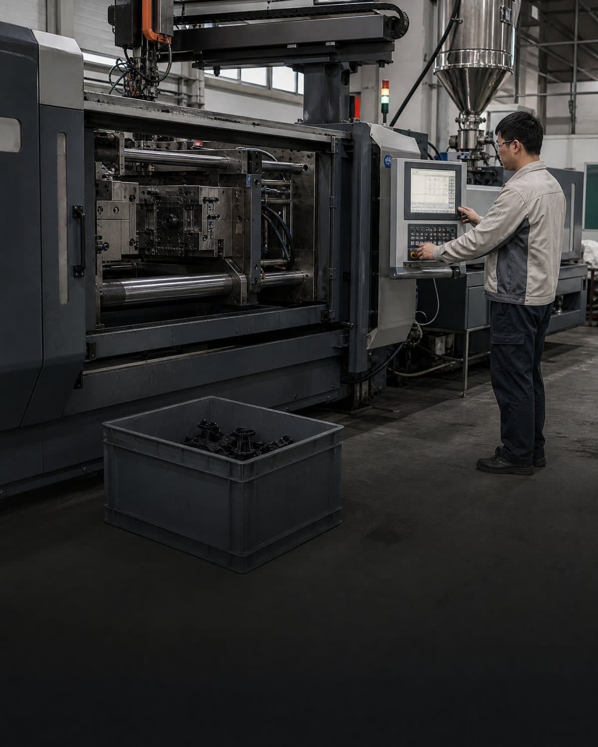
The hinge can determine the parting line, gate, runner, vent, ejection and tool-modification strategy. A thin web may need reliable filling without an unwanted knit line. A pinned hinge may require cores, slides, shutoffs or an assembly operation. A lid that must fold flat may need to be molded open or at a controlled angle to release from the tool. Ask for marked-up CAD showing the opening direction, parting line, gate and vent locations, ejection support, hinge clearances and any secondary trimming or pin insertion.
Ask bidders to disclose assumptions that affect both feasibility and price: cavity count, runner type, machine range, resin grade, melt and mold temperature basis, packing and cooling approach, expected cycle, automation, inspection method and packaging orientation. A quoted cycle time, price, tool life or yield is a programme-specific estimate until demonstrated on the released design and process. If a supplier proposes a different grade, gate face, hinge thickness, pin material or molding angle, route the change through engineering review rather than comparing it as an equivalent quote.
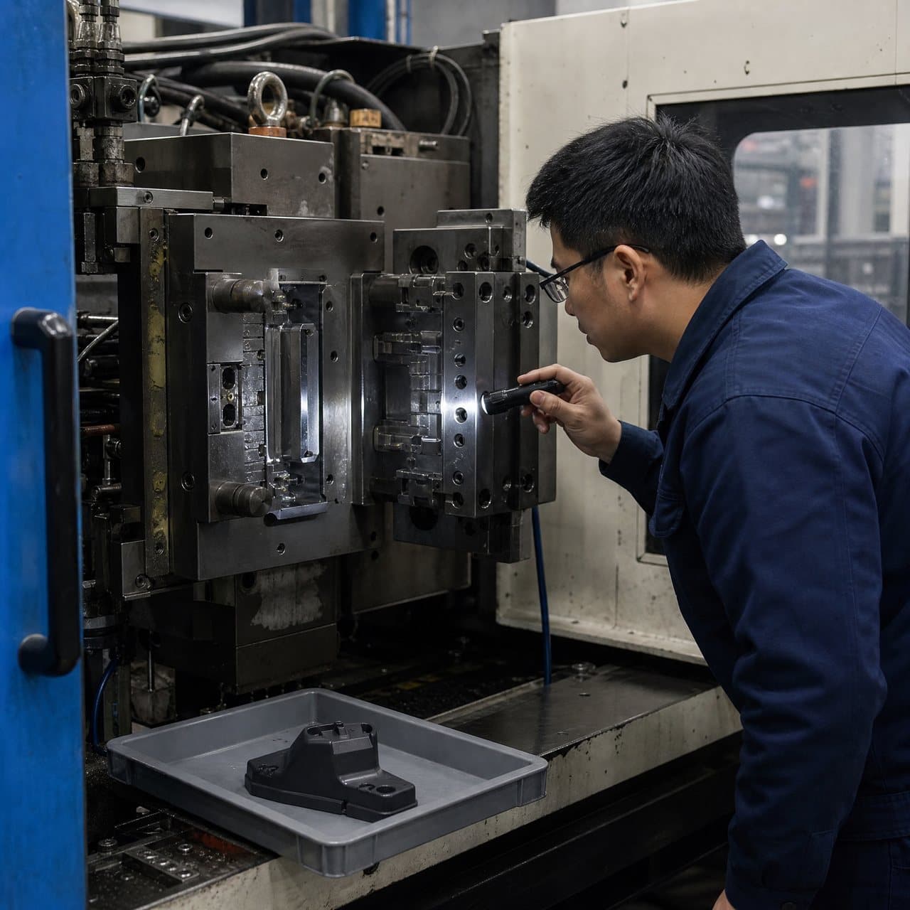
Measurement needs its own plan. Flexible webs can deflect under a probe, and hinge torque depends on angle, speed, fixture, lubrication, conditioning and mating-part friction. Define datums, free-state versus assembled dimensions, measurement force, optical or contact method, inspection timing after molding and cavity or lot sampling. Request DFM comments, a risk register, first-trial records, material certificates or lot records where required, and a clear deviation and corrective-action route.
05
5. Use staged validation and supplier approval gates
Gate 1—requirements: approve the hinge type, motion envelope, load cases, environment, mating parts, cosmetic zones, material restrictions, forecast and acceptance tests. Gate 2—design and tooling: approve the controlled CAD, hinge section, transitions, radii, gate and vent concept, parting line, ejection, pin or insert details, measurement method and open assumptions. Gate 3—sample approval: inspect critical dimensions and appearance, assemble the real mating parts, measure operating force or torque where relevant, and run the agreed flex, load or environmental tests. Gate 4—production readiness: confirm material traceability, process records, inspection frequency, reaction plan, packaging, change notification and any product-level qualification still required.
For a living hinge, the validation plan may include repeated opening and closing, maximum angle, operating force, environmental conditioning, chemical exposure, drop or abuse loads and visual checks for cracking or whitening. For a mechanical hinge, it may include static load, torque, backlash, retention, wear, pin insertion force, stop strength and repeated cycling. Select tests from the product failure modes. A short bench cycle or a single visual sample does not establish service life.
Before purchase-order release, require a written evidence matrix that links each requirement to its inspection or test, sample condition, acceptance limit, owner and approval gate. Ask for production-intent samples from the proposed tool, resin and process where the hinge is function-critical. If a result fails, define whether the response is a geometry change, resin change, tool correction, process-window study, additional test or formal concession. Record customer approval for product-impacting changes and do not treat a supplier capability statement as a substitute for evidence.
Practical takeaway
Before you move
to the next review.
- Define whether the hinge is a compliant living hinge, a pinned plastic hinge or a hybrid, and state the required motion, load, stop, retention and service function.
- Name the exact resin grade, colour and additive basis, then document temperature, chemicals, humidity, UV, cleaning, sterilization or other environmental exposures that can affect hinge behaviour.
- Provide controlled CAD and drawings marking hinge thickness, transitions, radii, shoulders, flow-sensitive zones, cosmetic areas, datums, mating parts and permitted gate, parting-line and ejector locations.
- Request supplier evidence covering DFM, gate and vent strategy, tooling assumptions, material traceability, measurement method, first-trial findings and any proposed geometry or resin substitutions.
- Approve production only after representative samples pass the defined dimensional, assembly, load, torque, flex-cycle and environmental tests, with deviations and change ownership documented.
FAQ
Common questions
What is the difference between a living hinge and a mechanical plastic hinge?
A living hinge is a thin flexible section molded into the same polymer part and is suited to an integrated flexing motion when the material and geometry can carry the required duty. A mechanical plastic hinge uses separate knuckles, a pin or another articulated feature and may better suit controlled rotation, higher load, a stop, replaceable hardware or a defined torque. The correct choice depends on the application, environment, assembly and validation requirements rather than on a universal cost or cycle-life rule.
What material is best for an injection molded living hinge?
Polypropylene is a common starting candidate, and some polyethylene grades may also fit, because their ductility and fatigue behaviour can support repeated flexing. There is no universal best grade. Melt-flow behaviour, copolymer structure, additives, colour, fillers, recycled content, temperature, chemicals, geometry, flow direction, tooling and customer specifications all matter. Approve the named grade using representative samples and the application test plan.
How thick should an injection molded living hinge be?
There is no universal thickness. Published design guidance often uses a thin web in a fraction-of-a-millimetre range, but the workable value depends on the resin grade, adjoining wall, hinge width, bend angle, transition radii, gate and vent layout, tool capability and required flex life. Use a supplier DFM review and a controlled steel-safe trial where practical, then confirm the actual part with dimensional and functional testing.
How should a buyer validate living-hinge life?
Define the real duty before testing: opening angle, speed, force, fixture, mating parts, temperature, humidity, chemicals, conditioning, cycle count and failure criteria. Test production-intent parts made with the proposed grade and tool concept, and include enough specimens to examine variation by cavity or lot when the risk justifies it. A generic claim such as millions of cycles, a room-temperature demonstration or a material data sheet is not proof of service life for the finished product.
References
Source material
- [1] Protolabs — Living Hinge Basics for Injection Molding
- [2] Fictiv — How to Design Living Hinges
- [3] Protolabs — Designing Living Hinges That Fold Flat
- [4] ASTM International — ASTM D638, Standard Test Method for Tensile Properties of Plastics
This guide is general information for early procurement and engineering discussion. It does not replace product-specific DFM, qualification, validation, regulatory assessment or legal advice.