
CNC, EDM, grinding and polishing are not interchangeable routes to a ‘better’ mold. Each changes a different risk: CNC injection mold machining establishes accessible geometry efficiently; EDM injection mold machining can form detail that cutters cannot reach; grinding controls selected datum surfaces; and injection mold polishing manages the surface seen by the resin and, ultimately, the part. The buyer’s task is to define what each critical surface must do before asking a supplier to choose a route. That means separating fit, sealing, release, texture, visible appearance and measurement needs rather than putting one finish note across the whole tool.
The practical comparison is therefore made at feature level. A shallow cosmetic cavity wall, a deep rib, a shut-off, a slide land and a clear-part surface may need different sequences and acceptance evidence. Surface-texture notation can communicate a technical requirement, but it does not on its own define visual acceptance, tool accessibility, molding release or product performance.[1] This guide helps procurement and engineering ask for a controlled finishing plan. It is not a universal process prescription; the final route needs supplier confirmation against the released CAD, steel, heat-treatment condition, resin, geometry and sampling plan.
A named finish alone is not a process plan. Ask the supplier to map each critical surface to its final operation, its measurable requirement, its visual acceptance basis and any post-EDM or post-polish control needed.
01
1. Start with the surface job, not the machine name
Begin with a color-coded tool or part map. Mark datums, sealing lands, shut-offs, ejection contact, gate areas, visible faces and texture zones. State the consequence of error—leak, flash, drag, poor fit or unacceptable gloss—so a cosmetic finish is not applied where flatness, wear resistance or edge control is the real need.
For each marked surface, provide CAD revision, resin and filler, demand, proposed steel and treatment, draft, gloss or texture intent, and mating or gauge context. The same roughness can result from different sequences with different geometry and repair implications. ISO 21920-1 sets notation rules for profile surface texture; it does not select a part-specific acceptance plan.[1]
| Surface decision | Input that changes the finishing route | Buyer evidence to request |
|---|---|---|
| Visible surface | Gloss, texture, resin appearance and permitted flow evidence | Appearance standard, viewing condition and finish-zone map |
| Seal, shut-off or locating land | Datum relationship, wear and edge definition | Datum-linked form or dimension check and final-operation note |
| Deep rib, slot or internal detail | Tool access, draft, corner and polish access | Section view, proposed route and inspectability confirmation |

02
2. Compare the four routes by access, geometry and residual risk
CNC injection mold machining usually starts accessible volumes, faces and contours. It offers programmed removal tied to CAD datums, but cutter reach, diameter, stiffness and clearance can limit deep features. Small-tool paths may leave scallops, while deflection or weak workholding can alter geometry. Ask which surfaces are finish-milled, what stock remains and how edges and references are protected.
EDM injection mold machining can form conductive-steel features beyond practical milling access, including deep details and fine internal corners. Sinker EDM reproduces an electrode; wire EDM mold machining follows a wire path for through profiles, inserts, slots and related details. Process settings and later skim, stoning or polish affect the surface. NIST notes EDM can produce a recast layer whose properties vary with workpiece and process; request feature-specific finishing and inspection rather than assume a defect.[2]
| Route | Where it can add value | Risk or limitation to resolve before release |
|---|---|---|
| Finish CNC milling | Accessible 3D form and datum-linked geometry | Confirm cutter access, scallops, workholding, stock and radius limits. |
| Sinker EDM | Deep or enclosed steel features | Confirm electrode datum, corner condition, surface target and polish access. |
| Wire EDM | Through cuts, inserts, slots and close-fit details | Confirm wire path, radius implication, taper and edge treatment. |
| Injection mold grinding | Flats, parallels, lands and references | Confirm datum setup, wheel access, stock, heat control and mark acceptability. |
| Injection mold polishing | Cosmetic, release-sensitive or optical-intent surfaces | Confirm finish target, directionality, edge protection, access and visual method. |
03
3. Review the sequence, because the last operation controls the delivered surface
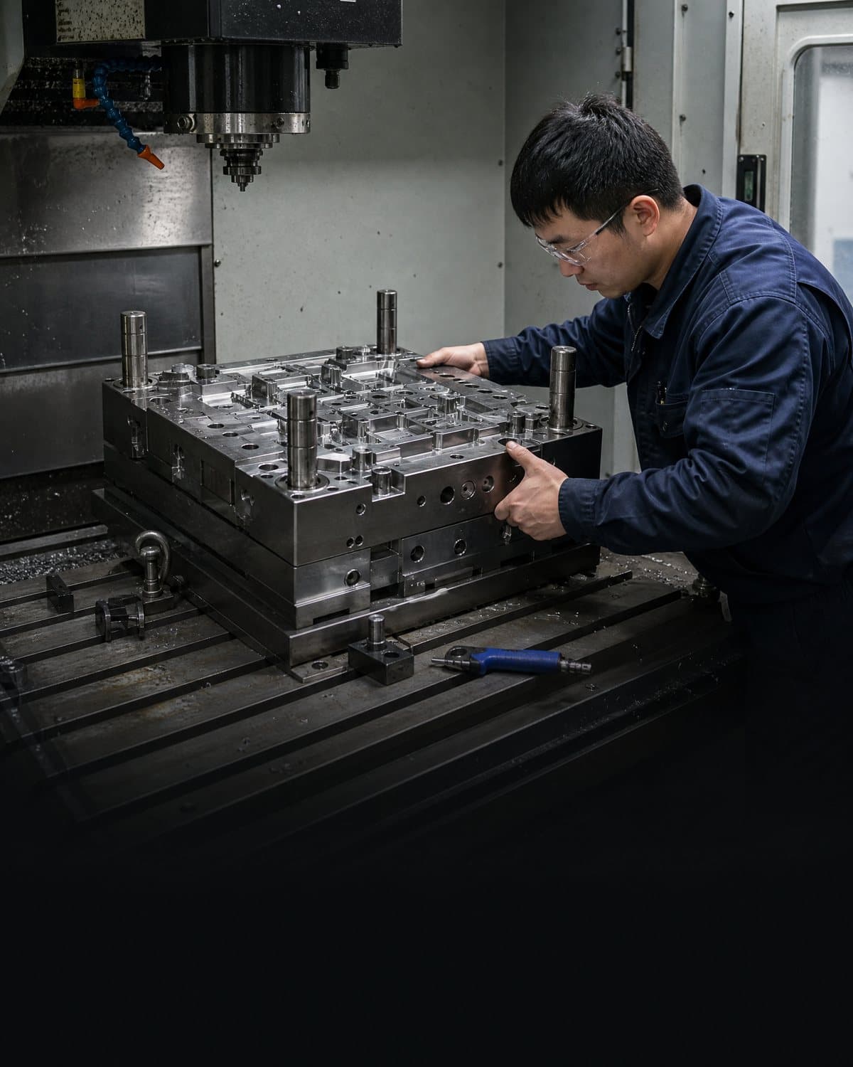
A credible plan shows sequence. Rough machining, treatment, finish machining, EDM, grinding, bench work, polishing, texturing and inspection can differ by feature and steel. Grinding may establish a datum, while later hand work can change an edge or blend. Polishing can remove marks; it cannot recover a location, flatness or profile error. Ask which operation establishes each critical characteristic.
A finish also affects release and appearance. Deep ribs can be difficult to polish; texture can need more draft than a polished wall; and high gloss can reveal a defect hidden on a matte part. Industry guidance notes that machined marks are normally followed by sanding and polishing and that inaccessible ribs and bosses should be addressed in tool design.[3] This is planning context, not a part-specific guarantee.
04
4. Accept the tool with layered evidence, not a blanket ‘mirror finish’ statement
Tool acceptance should test the claim. For geometry, request datum-linked tool or part inspection with a defined condition. For texture, state the parameter, direction where relevant, area, instrument condition and limit. For appearance, use agreed lighting, sample resin and color, zone map and visual standard. A surface meter supports a defined texture decision but cannot alone judge molded gloss.
Link evidence to tool and cavity or insert ID, drawing revision, finishing status, resin and color, trial date and deviations. Review molded samples separately because flow, pack, cooling and release can change appearance. If machine, electrode, polish sequence or steel changes, ask whether re-inspection or re-sampling is needed. The buyer retains product-acceptance authority; the supplier must confirm departures from the plan.
| Acceptance layer | Useful evidence | Question that prevents ambiguity |
|---|---|---|
| Tool geometry | Selected datum, land or insert inspection | What is the agreed measurement setup? |
| Steel surface | Finish-zone map, texture record and deviation log | Is it measured, visually judged, or both? |
| Molded part | Cavity samples, appearance and functional checks | Which resin, condition and viewing rule apply? |
| Change control | Before/after record and requalification decision | Who authorizes it and what must be repeated? |
Practical takeaway
Before you move
to the next review.
- Map each critical tool and part surface to its functional, cosmetic, release or reference role.
- Provide the released CAD, resin, draft, steel, treatment and visual-finish inputs before the supplier selects processes.
- Request a feature-level sequence that identifies final CNC, EDM, grinding, polishing or texture operations.
- Define tool-side measurements and molded-part appearance checks separately, with the relevant acceptance condition.
- Control deviations, repairs and route changes through written supplier confirmation and a defined re-inspection decision.
FAQ
Common questions
Is CNC injection mold machining always preferable to EDM?
No. Finish CNC milling is often efficient for accessible geometry, but EDM may be more suitable for particular deep, enclosed or fine steel features. Compare access, datum control, corner condition, surface requirement, steel condition and later finishing before choosing a route.
Can injection mold polishing correct a dimensional issue?
Not reliably. Polishing removes material and can change edges or local form. It may improve surface appearance or release, but a location, profile or flatness issue needs a supplier-reviewed corrective route and fresh evidence against the controlled requirement.
What should an RFQ say about injection mold grinding and wire EDM?
Mark the affected surfaces and state their function, datum relationship, geometry, corner or edge intent, finish target and acceptance evidence. Ask the supplier to confirm access, sequence, inspection method, remaining risks and any alternative tool construction before award.
References
Source material
- [1] International Organization for Standardization, ISO 21920-1:2021, Geometrical product specifications (GPS) — Surface texture: Profile — Part 1: Indication of surface texture.
- [2] National Institute of Standards and Technology, Effect of Electrical Discharge Machining (EDM) on Miniaturized Charpy Test Results.
- [3] Fictiv, Injection Molding Finish Options: Polishing and Texturing.
- [4] ISO, ISO 20457:2026, Plastics moulded parts — Tolerances and acceptance conditions.
This guide is general information for early procurement and engineering discussion. It does not replace product-specific DFM, qualification, validation, regulatory assessment or legal advice.