
Carbon-fiber-reinforced injection molding can help an OEM reduce mass or preserve stiffness while redesigning a plastic component, but it is not a universal lightweighting solution. Short carbon fibers change the selected resin's modulus, flow behavior, shrinkage, surface appearance and directional performance. The result depends on the resin family, fiber loading and length, geometry, gate and flow path, processing conditions, environment, annual volume, tooling strategy and customer specifications.
For procurement and engineering teams, the right question is not whether carbon fiber is stronger than unfilled plastic. It is whether a named compound and part design can meet the required stiffness, impact, dimensional, durability and appearance targets at an acceptable total cost, with evidence from the actual molded configuration.
Decision rule: approve a carbon-fiber grade, part geometry, tool concept and validation plan together; do not approve a fiber percentage or a generic data-sheet value in isolation.
01
When carbon-fiber reinforcement is a credible lightweighting route
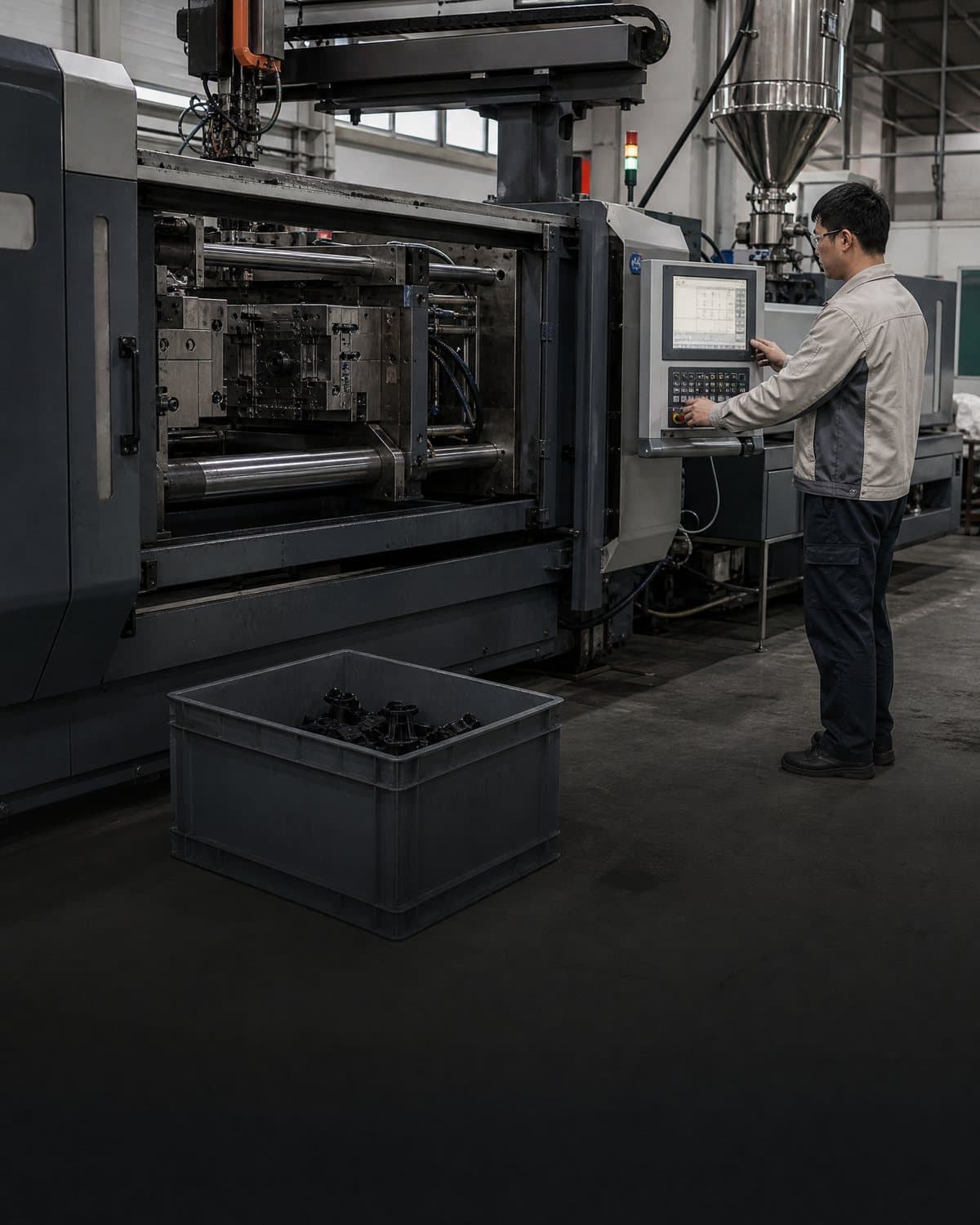
Start with the end-use requirement and the baseline part. Record current mass, load cases, deflection limits, impact events, fatigue or vibration concerns, temperature and humidity range, chemical exposure, electrical requirements, cosmetic zones, assembly interfaces and target life. Separate requirements from recommendations: the requirement may be a maximum mass or a defined deflection under load, while a recommendation may be to evaluate a carbon-fiber-filled polyamide or PEEK grade. The recommendation must remain open until the actual design and test evidence support it.
Short carbon fibers can raise stiffness and may permit a thinner wall or fewer reinforcing features in some geometries. That does not guarantee lower mass. A part may need added ribs, thicker local sections, larger radii, inserts or a different safety factor after impact, fatigue, thermal or assembly review. Carbon fiber can also reduce ductility and change failure behavior. Compare the candidate against the unfilled baseline and any glass-fiber, long-fiber or metal alternative using the same functional acceptance criteria.
Weight reduction should be calculated at assembly level, not only from resin density. Include fasteners, inserts, coatings, seals, brackets, secondary operations and any tool or assembly changes. A higher-cost compound may be justified by a validated mass or performance benefit, but neither cost reduction nor cycle-time improvement should be assumed. Volume, material availability, machine capability, scrap route and customer-approved substitutions can change the business case.
02
Choose the material by directional performance and application fit
Injection-molded short-fiber composites are anisotropic: fiber orientation follows melt flow, so stiffness, strength and shrinkage can differ by direction. ISO 294-5 describes a standard plate approach for investigating anisotropy. Use plaques or molded test pieces to understand a candidate, but do not transfer their values directly to every rib, boss, weld line or thin wall.
This comparison is a screening framework, not a universal ranking. Ask for the exact resin manufacturer, grade, fiber content, color, conditioning state, data-sheet revision and test direction. Check the selected compound against the actual temperature, moisture, chemical and load environment.
Request information about fiber length retention, drying or conditioning, recyclate limits, surface requirements and material substitutions. For demanding structures, specify whether evidence represents flow direction, transverse direction, weld-line areas or the finished part.
| Candidate route | Potential fit | Main buyer checks |
|---|---|---|
| Short carbon-fiber thermoplastic | Parts where stiffness, dimensional control or electromagnetic properties are important and geometry can use flow direction deliberately. | Exact fiber loading and grade; directional modulus and strength; impact retention; moisture and temperature effects; surface and weld-line behavior; material availability. |
| Short glass-fiber thermoplastic baseline | A useful comparator when stiffness, cost or broad grade availability matters and carbon-fiber conductivity or appearance is not required. | Mass versus stiffness; anisotropic shrinkage; impact; corrosion or electrical constraints; fiber print; price and approved supply route. |
| Unfilled engineering thermoplastic | Parts prioritizing ductility, impact tolerance, appearance or simpler recycling where stiffness can come from geometry. | Wall thickness and ribs; creep and temperature; deflection; chemical exposure; safety factor; whether the weight target is met. |
| Metal or continuous-fiber alternative | Highly loaded, fatigue-critical or directionally demanding structures that may not suit short-fiber molding. | Total assembly mass; joining and tooling; corrosion; production rate; repairability; anisotropy; qualification burden and customer design rules. |
03
Design for stiffness without creating impact, shrinkage or warpage surprises
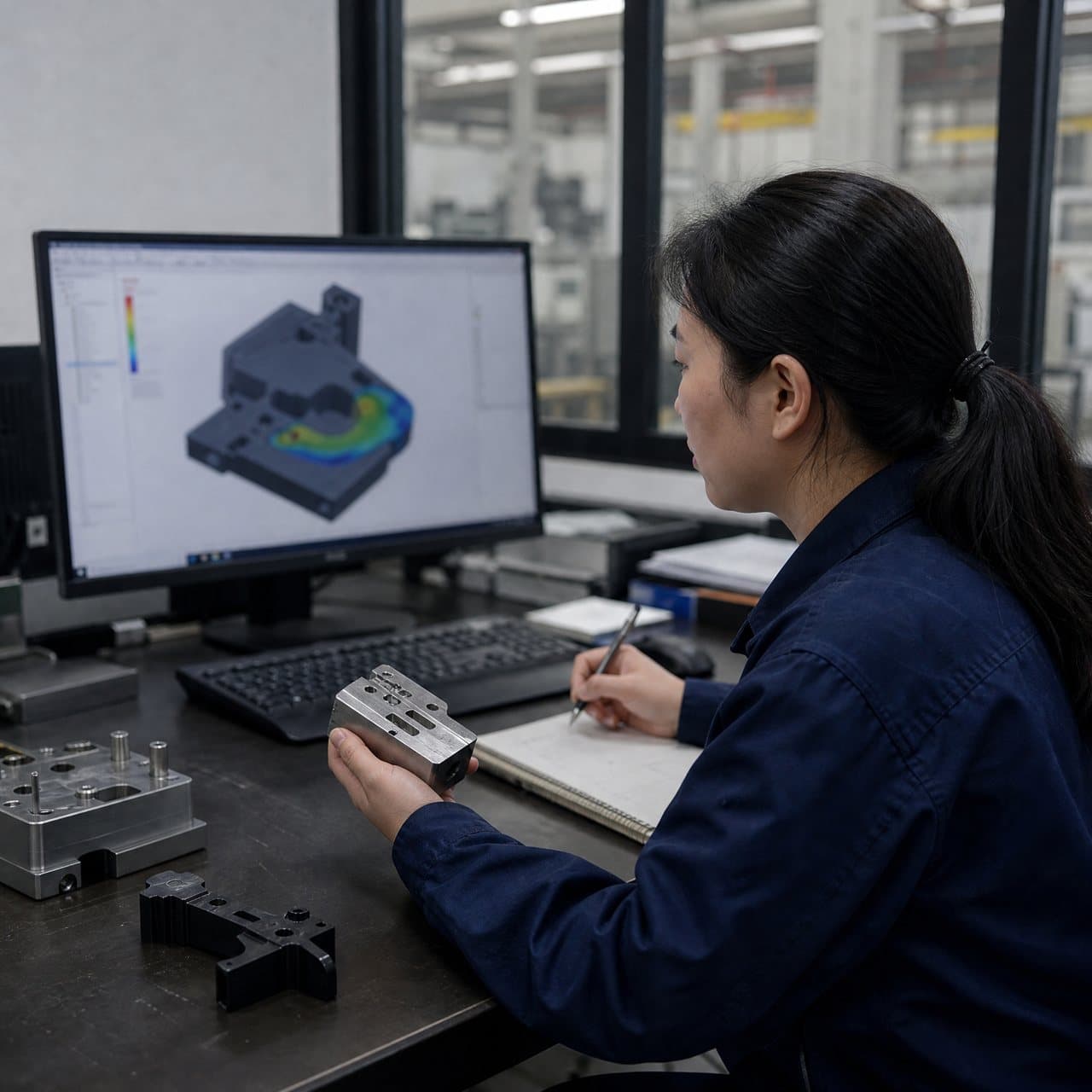
Lightweighting often shifts material into ribs, webs, bosses or local reinforcements. Review nominal wall transitions, rib-to-wall ratios, draft, radii, knit-line locations, gate position, vents, ejection and fastener loads with the selected compound. A carbon-fiber-filled grade may fill differently from its unfilled counterpart, and orientation can make a part stiff in one direction but less capable in another. Simulation can screen flow, orientation, packing and deformation, but physical validation is still required for the released design.
Fiber orientation can reduce shrinkage along the flow while leaving transverse or thickness-direction behavior different. Uneven orientation, packing, cooling, wall thickness and tool temperature can produce warpage or twist. Do not promise a lower shrinkage value or a flat part without part-specific evidence. Establish datums, measurement temperature and conditioning state, then compare a controlled sample to the released drawing and functional interfaces.
Impact is a separate question from tensile modulus. A stiffer, lighter part may transmit more load or crack at a notch, weld line, boss or insert under an impact event. Define the relevant impact method, energy, temperature, conditioning, failure criterion and assembly state. If a customer requirement is stated at component or vehicle level, test the component in the relevant boundary conditions rather than relying only on a resin plaque.
04
Align tooling and processing with the fiber orientation plan
Gate location is a product decision because it influences fiber orientation, weld lines, pressure, surface appearance and the direction of principal stiffness. Review single- versus multi-gate filling, runner balance, gate vestige, venting, flow length and potential knit lines before tool release. A gate that improves fill may place a weld line in a loaded feature; a cosmetic gate choice may create an unfavorable orientation for a bracket or beam. Record the accepted trade-off and the evidence supporting it.
Tooling must account for the compound's shrinkage behavior, abrasive fiber content, ejection loads and expected production volume. Steel selection, cavity and core wear, vent maintenance, replaceable inserts and measurement access should be discussed with the toolmaker. No universal tool life, tolerance, cycle time or maintenance interval applies across resin grades, fiber loadings, geometries and machines.
At process development, define the approved material condition, melt and mold-temperature window, fill and pack profile, screw and back-pressure settings, drying or conditioning controls where relevant, cavity balance, part cooling and start-up disposition. The window should be linked to critical characteristics such as mass, dimensions, deflection, surface, conductivity or assembly fit. A stable process is not established by one good sample or by copying settings from an unfilled grade.
05
Use evidence and approval gates before committing the lightweight design
At RFQ, provide the controlled CAD and drawing revision, baseline mass, load cases, target mass or stiffness, environment, cosmetic zones, annual volume, required markets and customer specifications. Ask suppliers to return the proposed grade and fiber loading, material data-sheet revision, assumptions, DFM risks, flow-orientation analysis approach, tool concept, cost basis, lead-time assumptions and alternatives. Require written notice before changing resin source, grade, fiber content, colorant, regrind policy, tool, cavity or process conditions that could affect approved performance.
Request evidence in layers. Material evidence can include current grade data and test methods. Process evidence can include drying records, lot traceability, machine and cavity identification, parameter records and first-off results. Part evidence should include mass, critical dimensions, warpage, surface, assembly fit and the agreed mechanical or environmental tests. ASTM D638 is one tensile test route for rigid and semi-rigid plastics, but the test method and specimen direction do not by themselves qualify a molded component; select the method and acceptance criteria for the actual product risk.
Use approval gates: first, requirements and baseline agreement; second, material nomination and DFM review; third, tool and simulation release; fourth, traceable trial parts and dimensional or functional review; fifth, qualification and customer release; and finally, production change control. Stop or reopen the decision if the actual grade, fiber content, flow direction, geometry, process window or environment changes materially. The product owner, not the supplier alone, should approve the final safety and compliance conclusion.

Practical takeaway
Before you move
to the next review.
- Define the baseline mass, load cases, deflection, impact, temperature, moisture, chemical, appearance and customer requirements before selecting a carbon-fiber grade.
- Compare the exact resin grade and fiber loading against unfilled, glass-fiber and other feasible routes using part-level mass, stiffness, impact and cost criteria.
- Review gate location, fiber orientation, weld lines, shrinkage, warpage, ribs, bosses, inserts, ejection and tool wear in a documented DFM and tooling review.
- Request grade-specific data, test direction and conditioning, material traceability, processing controls, simulation assumptions and first-article evidence.
- Set approval gates for requirements, material and DFM, tooling, trial parts, qualification and change control before production release.
FAQ
Common questions
Can carbon-fiber-reinforced injection molding always reduce part weight?
No. Carbon fiber can raise stiffness or help preserve performance at a lower section in some designs, but the final mass depends on resin density, fiber loading, geometry, safety factors, inserts, ribs, assembly interfaces and customer requirements. Validate the complete part or assembly against the baseline.
Is carbon-fiber-filled plastic stronger in every direction?
No. Injection molding aligns short fibers with melt flow, so modulus, strength and shrinkage can be directional. Gate location, flow length, weld lines, local geometry and processing affect the result. Request directional and part-relevant evidence rather than relying on one isotropic data-sheet number.
What should a buyer request from a carbon-fiber injection molding supplier?
Request the exact resin manufacturer and grade, fiber content and form, data-sheet revision, conditioning and processing requirements, DFM and flow-orientation risks, tooling concept, traceability plan, proposed inspection and test methods, change controls, cost assumptions and evidence for the actual molded configuration.
Does carbon fiber reduce warpage and shrinkage?
It can change and sometimes reduce shrinkage in a particular direction, but it can also increase anisotropy and cause twist or warpage when orientation, cooling, packing and geometry are unbalanced. Use material-specific simulation and molded-part measurement; do not assume a universal improvement.
References
Source material
- [1] ISO 294-5:2026, Plastics — Injection moulding of test specimens — Part 5: Preparation of standard specimens for investigating anisotropy
- [2] ISO 294-1:2017, Plastics — Injection moulding of test specimens of thermoplastic materials — Part 1: General principles
- [3] ASTM D638 overview, tensile properties of plastics and specimen considerations
- [4] ASTM D790, flexural properties of unreinforced and reinforced plastics
This guide is general information for early procurement and engineering discussion. It does not replace product-specific DFM, qualification, validation, regulatory assessment or legal advice.