
A mold can fill parts successfully yet still be a poor production asset if its ejection system returns inconsistently, drags parts, damages a cosmetic face or loses alignment. The injection mold ejector plate transfers machine force to pins, sleeves, blades or other part-contacting elements. Injection mold return pins help return that moving assembly as the mold closes. Reliability therefore depends on the complete tool, part, press and service arrangement—not one component specification.
For buyers in Europe, the US and the Middle East, the procurement question is what evidence shows that this specific ejection arrangement can operate within agreed tool, material and press assumptions. This guide defines practical decisions, inputs, risks and acceptance evidence. The injection mold manufacturer should confirm product-specific dimensions, force limits and service provisions against the released design and production plan.
Treat ejection as a controlled motion system. A clean part from a short trial does not, by itself, establish return consistency, wear life, press compatibility or safe recovery after a stoppage.
01
1. Turn the ejection concept into a buyer decision
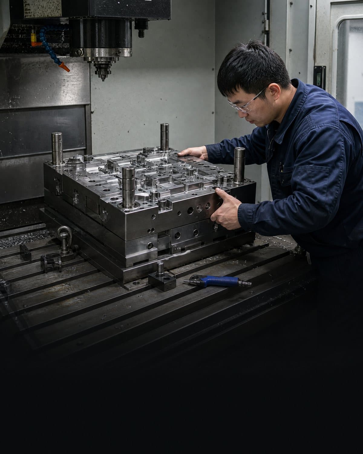
Define what the system must protect and prove. Deep ribs, textured walls, thin cosmetic panels, inserts, flexible features and multiple cavities can change force distribution and failure modes. The released CAD or drawing should identify surfaces where ejector witness, distortion or drag is unacceptable, plus features that could shift under uneven push. ISO 20457 is useful for discussing molded-part tolerances and acceptance conditions, but does not replace a product-specific ejection review.[1]
Before tool build is frozen, request a concise concept record: part orientation; ejector types and locations; plate travel; return-pin locations; any guided or sequenced motion; press interface; and service access. If a pin touches a visible surface or a return pin has a locating role, the supplier should explain the trade-off and failure consequence. Approval should cover the stated concept and risk controls—not unrecorded assumptions about resin, press or production rate.
| Input to control | Decision it supports | Supplier confirmation needed | Risk if unclear |
|---|---|---|---|
| Released part revision and cosmetic/CTQ map | Where ejection marks, force or distortion matter | Which surfaces and features drive the ejector layout | A functional pin location may become an unapproved visible defect |
| Mold and press interface assumptions | Whether the tool can complete and return its stroke | Ejector coupling, stroke, force direction and any safety or sensor dependency | A capable tool may be paired with an unsuitable machine setup |
| Production material and cavity plan | How trial evidence can be applied | Resin grade, conditioning, cavity identity and expected operating envelope | Release behavior and shrinkage may be misread from nonrepresentative samples |
02
2. Recognize the reliability risks behind a moving plate
The injection mold ejector plate should move squarely, complete its stroke and return without binding before closing. Reliability follows the full load path: machine coupling, plate guidance, pin fits, return pins, springs where used, lubrication, clearance, contamination control and the molded part’s resistance. A sticking part can create uneven load; a bent pin, worn guide or loose retainer can then produce damage, flash or a plate that does not seat.
Return issues can remain hidden until closing. Their task is commonly to bring the ejection assembly back, but sequence and load path vary by design. Do not assume a standard number, size or preload. Ask how positive return is achieved, what prevents a plate from remaining forward, and how incomplete return will be found before it damages shutoffs or parting surfaces. Apply greater scrutiny to high-cavitation, abrasive-resin, short-cycle, complex-motion, automated and cosmetic tools. The supplier should justify any wear material, sensor or spare against that risk.
03
3. Request trial evidence that separates function from durability claims
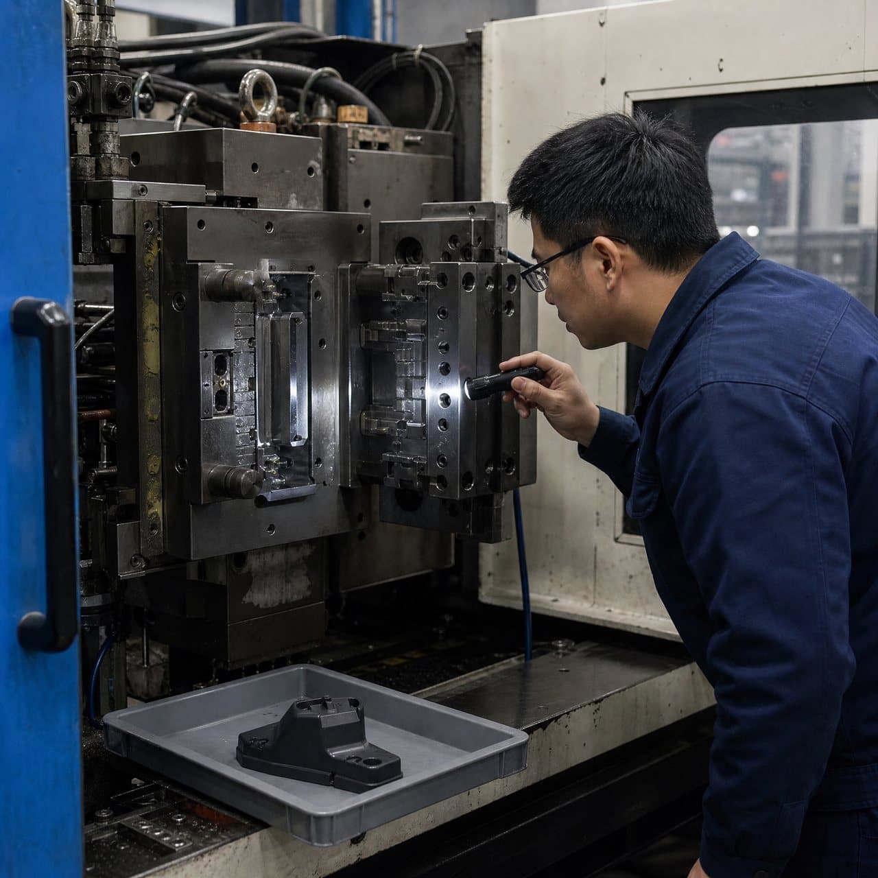
At bench review and trial, identify the exact tool revision, insert configuration, material and press. A controlled demonstration should show opening, forward ejection, part release or handling, return and closing. Record sample and cavity context where relevant. Look for part drag, pin witness, stress whitening, distortion, damaged ejectors, abnormal plate motion, inconsistent return, interference and unexplained manual assistance. These findings describe the demonstrated state, not a universal life guarantee.
For narrow clearances or small shifts, agree the measurement method and traceable sample identity. ASME Y14.5 supports a common language for tolerancing, but does not establish acceptance criteria or prove an inspection system.[2] Confirm measured features, datum approach, tool condition and changes made before sampling. Agree the run purpose—release confirmation, cavity comparison, defined cycles, process window or production-oriented study. If life is estimated, request its basis, exclusions, maintenance interval and invalidating conditions.
| Evidence | What it can support | What it cannot establish alone |
|---|---|---|
| Recorded controlled ejection sequence | Plate travel, return sequence and obvious interference at the shown tool state | Long-run wear, machine-to-machine repeatability or part conformance |
| Identified samples and focused inspection | Part release, marks, distortion and listed critical-feature results | Acceptance of unmeasured features or a different resin/condition |
| Declared trial log and corrective-action record | Traceability of observations and next changes | Proof that a corrective action remains effective after extended use |
04
4. Make serviceability and handover part of acceptance
Reliable injection mold maintenance starts with a clear baseline. At handover, request an ejection-system drawing or service view; a list identifying pins, sleeves, blades, return pins, springs and guides; approved lubricants where relevant; and replacement instructions. Confirm access, special tools, assembly cautions and spare scope. A spare must be traceable to the tool and specification; a visually similar component may not be suitable.
Set maintenance triggers rather than promise one universal interval: planned cycles, visible marks, rising release difficulty, inconsistent stroke, contamination, teardown wear, material change or a crash. The molder should log tool ID, symptom, cavity where relevant, action and replacement component. At acceptance, the supplier should identify the as-built configuration, open risks and receiving-press checks. Agree who may alter hardware, approve substitutions and require post-change trial or remeasurement. ANSI/PLASTICS B151.1 addresses injection-molding-machine safety but does not replace tool-specific risk assessment.[3]

Practical takeaway
Before you move
to the next review.
- Approve a controlled ejection concept that links part revision, visible/critical surfaces, ejector layout, return method and the intended press interface.
- Ask the supplier to identify the complete load path and to confirm how incomplete return or plate misalignment will be detected before damage occurs.
- Witness or review an identified sequence through opening, ejection, release, return and closing; record any manual intervention, substitute material or temporary condition.
- Make durability claims conditional: agree the trial purpose, material, cavity scope, cycle basis, exclusions and the evidence required after a tool or process change.
- Receive ejection-service documentation, traceable spare-part identification and written responsibility for maintenance, hardware changes and post-change confirmation.
FAQ
Common questions
Are return pins the same as ejector pins?
No. Ejector pins normally contact the molded part to help release it. Injection mold return pins generally act on the ejection assembly during closing to help return it to position. Exact functions and sequences vary, so ask the supplier to confirm the tool-specific design.
Can a successful T0 or T1 trial prove ejector-plate reliability?
It can show the behavior observed under the recorded trial conditions. It does not by itself prove long-run wear, production-press compatibility or performance with a different resin, cycle time or maintenance practice. Agree any further run, inspection or validation evidence in writing.
What should be included in an ejection-system spare-parts plan?
Request a tool-specific, traceable list of wear-prone components, quantities, material or coating identifiers where relevant, storage requirements, replacement cautions and the supplier contact for technical confirmation. The right scope depends on the tool’s duty, resin and service strategy.
References
Source material
- [1] International Organization for Standardization, ISO 20457:2018, Plastics moulded parts — Tolerances and acceptance conditions.
- [2] ASME, Y14.5 — Dimensioning and Tolerancing.
- [3] Plastics Industry Association, ANSI/PLASTICS B151.1 — Safety Requirements for Injection Molding Machines.
- [4] National Institute of Standards and Technology, Engineering Metrology Group.
This guide is general information for early procurement and engineering discussion. It does not replace product-specific DFM, qualification, validation, regulatory assessment or legal advice.