
Spare parts are not simply a purchasing list. For an export mold, they are a controlled way to recover function without quietly changing a critical interface, cavity surface, gate, or motion system. Buyers in Europe, North America, and the Middle East should compare injection mold spare parts with the approved tool revision, resin, process window, critical-to-quality features, and consequence of failure. Physical fit alone does not establish that material, finish, coating, heat treatment, or revision is suitable.
There is no credible universal shot-count, clearance, or dimensional limit for every tool. Wear depends on the resin, fillers, lubrication, mold temperature, alignment, clamp conditions, geometry, cleaning practice, storage, and the component’s duty cycle. The useful buyer question is therefore not, ‘What is the standard wear limit?’ It is, ‘What measured condition or production symptom requires action on this specific tool, and what evidence proves the tool is acceptable after the action?’
Buyer principle: classify each spare by the risk of its failure, define a tool-specific acceptance condition before it wears, and retain the before-and-after evidence with the mold record. Treat any published cycle interval as supplier- and design-specific guidance, not as a universal replacement rule.
01
1. Begin with a risk-based spare-parts map
Ask the toolmaker or molder for a bill of materials separating standard, custom, and proprietary components. Identify manufacturer and part number where applicable, drawing revision, material or treatment, installed quantity, interchangeability, storage location, and the feature or motion protected. This is stronger than a generic recommended-spares list because it shows which parts require controlled sourcing.
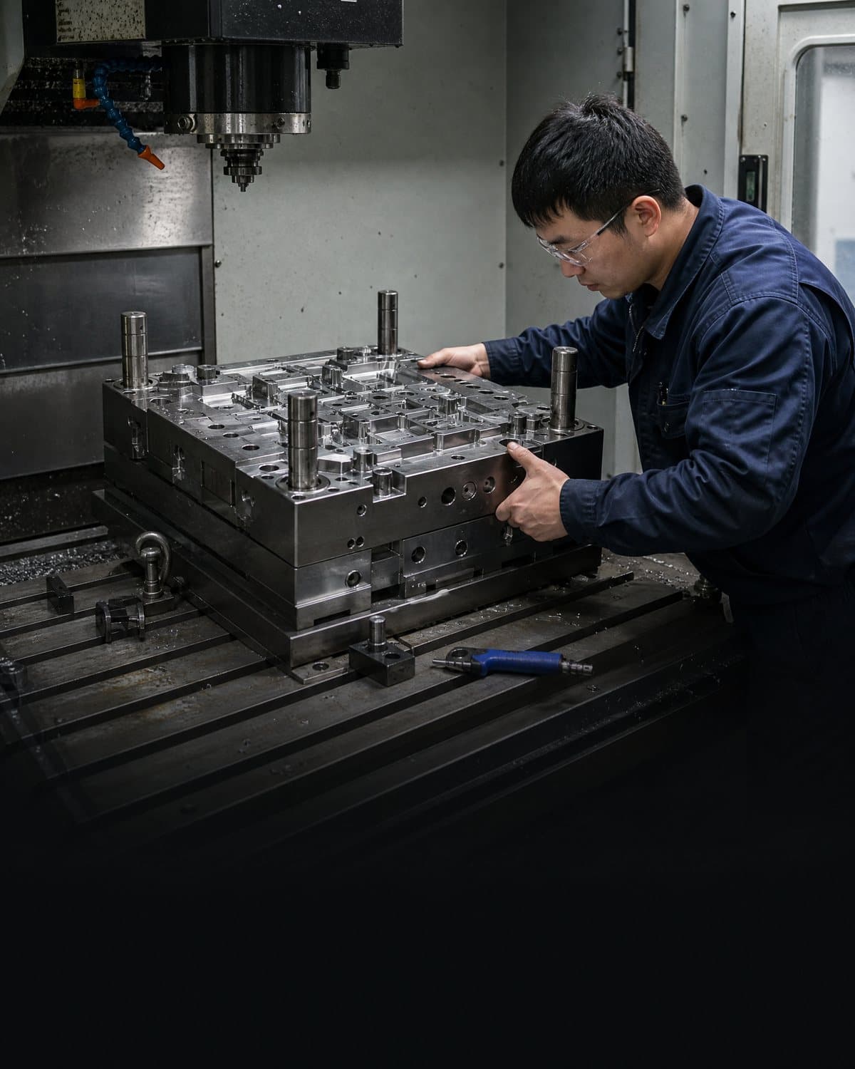
Prioritize components whose failure can create a quality escape, tool damage, safety concern, or long stoppage. Typical review candidates include an injection mold guide pin and bushing, interlocks and wear plates, slides or lifters, springs, return pins, an injection mold ejector pin and sleeve, cavity or core inserts, seals, cooling fittings, and hot-runner service parts. Wear in leader pins and bushings can disturb mold-half alignment; DME notes that poor alignment can lead to dimensional problems, flash, damaged components, or a mold that cannot run [1].
Classify spares by consequence rather than unit cost. For multi-cavity tools, record whether a part is common to all cavities or uniquely fitted to one location. This prevents an emergency replacement from creating an untracked cavity-to-cavity difference.
| Spare group | What the buyer should control | Trigger to investigate |
|---|---|---|
| Alignment and guidance | Drawing revision, mating component, lubrication method, baseline fit | Uneven flash, witness marks, difficult closing, asymmetric wear |
| Ejection and motion | Installed position, stroke clearance, contact surfaces, functional check | Sticking part, abnormal ejection force, bent or marked pins |
| Forming inserts and shutoffs | Cavity ID, approved texture or polish, datum and inspection points | Flash, cosmetic change, dimension drift, local damage |
| Hot runner system | OEM part number, zone or drop identity, seal and electrical records | Leakage, unstable gate, temperature fault, actuation issue |
02
2. Set wear limits from function, baseline, and measurement method
A wear limit should describe the loss of function the tool can no longer accept, not a borrowed spreadsheet number. Begin at acceptance or after a qualified rebuild. Capture reference photos, critical dimensions, cavity identity, surface condition, ejection operation, alignment contacts, and the part-quality baseline. Link each limit to a controlled method such as a named gauge, CMM routine, contact-pattern check, stroke observation, leak check, or approved part measurement. Name the decision owner and tool-stop point.
Use three conditions for each high-risk item: monitor, plan replacement, and remove from production. Monitor may be a visible change with no demonstrated effect on the approved part. Planned replacement is a measured trend or repeatable symptom that permits a controlled window. Removal is a condition that risks a critical requirement, damages a mating surface, compromises safe motion, or cannot be assessed reliably. Set the boundaries with the tool drawing and validation evidence.
Do not assume a visible defect proves a spare is worn. Flash can involve alignment, clamp condition, process pressure, or shutoffs. Burn marks can involve venting and process settings; DME notes that vents may become smaller through wear and may need restoring to their original depth [2]. Require a root-cause record, then compare tool and parts against the same baseline after repair.
| Decision level | Evidence | Buyer action |
|---|---|---|
| Monitor | Recorded trend or visual change; part remains within agreed acceptance | Set next inspection and retain traceable record |
| Plan replacement | Measured degradation or repeatable symptom; qualified window available | Approve spare identity, scope, and re-verification |
| Remove from production | Risk to CTQ, safe movement, mating surface, or stable process | Contain parts and define restart evidence before release |
03
3. Review the replacement package, not only the part
Before release, request component identification and fit-for-purpose evidence suited to the risk. For a custom insert, this can include drawing revision, material and treatment declaration, dimensional report against named datums, surface requirement, cavity location, and any hand-fitting record. For a standard component, retain manufacturer reference, size, configuration, and mating-part compatibility. Catalogue dimensions alone do not establish equivalence.
For guidance and moving components, ask how the supplier will check parallelism, return, free movement, lubrication, interference, and contact patterns after assembly. Meusburger offers both standard and self-lubricating guide bushes, showing why the lubrication approach and exact configuration should be recorded [3]. Preserve removed parts when practical if their condition could reveal a wider issue.
Hot-runner changes need OEM-specific discipline. Record each affected drop or zone, nozzle or valve-stem identity, applicable heater and thermocouple checks, seal work, and start-up result. Husky identifies distinct wear parts for hot-tip and valve-gate designs and publishes intervals for specified Husky platforms [4]. Those intervals inform OEM discussion; they do not establish a limit for another system, resin, or process.
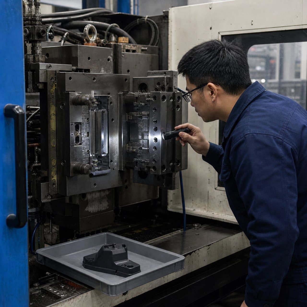
After installation, define a proportionate restart package: dry cycling, temperature or cooling checks, first-off review, targeted dimensions, cavity identification, and comparison with the approved sample or control plan. Escalate evidence when the item affects a critical feature, shutoff, melt delivery, or unexplained quality event.

04
4. Keep spares usable through traceability and preventive review
Inventory control matters as much as quantity. Store critical injection mold spare parts in protected, labeled locations with revision, tool ID, cavity or position, source, receipt date, and preservation needs. Keep matched sets together where one new part against a worn mate could alter fit. For stored molds, protect components from contamination and corrosion. Mold-Masters cautions users of its system to inspect idle ball screws for oxidation and dirt, then clean and lubricate before start-up [5].
Review consumption and inspection history during planned maintenance. Repeated injection mold repair of the same pin, bushing, insert, or gate may indicate misalignment, inadequate lubrication, resin abrasion, process imbalance, handling damage, or an unsuitable specification. Record the observed wear pattern, likely cause, corrective action, affected components, and verification result. Use the feedback to update the spare-parts map and next review.
For cross-border programs, agree who may authorize a substitute, who owns inspection records, how urgent parts are identified, and what evidence is required before production restarts. This keeps maintenance decisions auditable across time zones without promising a universal stock level, tool life, delivery time, or outcome.
Practical takeaway
Before you move
to the next review.
- Obtain a revision-controlled spare-parts map with tool location, source, and interchangeability status.
- Rank each item by its effect on part CTQs, tool damage, safe motion, and production interruption.
- Document tool-specific baseline measurements, photos, and the inspection method for high-risk interfaces.
- Define monitor, planned-replacement, and removal conditions with named decision owners and restart evidence.
- Archive the removed-part condition, replacement identity, root-cause finding, and post-repair verification.
FAQ
Common questions
What injection mold spare parts should a buyer keep?
Keep the decision risk-based. Start with items that are difficult to source, proprietary, custom-fitted, or capable of stopping production or damaging the tool: critical guidance components, ejection parts, motion-system wear items, key inserts, seals, and OEM hot-runner wear parts. The correct stock level depends on the tool configuration, service arrangement, lead-risk assessment, and ability to verify a replacement. Ask for a tool-specific list with part IDs and position data instead of accepting a generic kit.
How do buyers set an acceptable wear limit for a mold component?
Set it from the component’s function and the approved tool baseline. Identify the surface or movement that matters, the measurement or observation method, the part feature or process risk it protects, and the escalation point. A limit might be linked to repeatable alignment, shutoff condition, pin movement, cavity dimension, leakage, or a part-quality trend. The number, if one is needed, should come from the released drawing and validated application, not from a universal rule.
Can a non-OEM hot-runner spare be used?
Only after a controlled technical review. Hot-runner components can depend on exact material, coating, thermal, sealing, electrical, and tolerance characteristics. Obtain the OEM reference and confirm compatibility with the specific system and drop before authorizing a substitute. Record the decision and verify the repaired system at start-up. If the supplier cannot establish equivalence, treat the substitution as an engineering change rather than routine maintenance.
What evidence should be reviewed after injection mold repair?
Review what was changed, why it was changed, and how the result was checked. At minimum, retain component and revision identity, affected tool position, observed condition, root-cause assessment, installation record, and targeted functional or part inspection. The appropriate depth of re-validation increases when the repair affects a critical feature, cavity surface, precision shutoff, ejection, or melt-delivery path. Use the same approved inspection method used to establish the baseline whenever possible.
References
Source material
- [1] DME, Mold Interlocks: Challenges of Alignment
- [2] DME, Trouble Shooting: Burn Marks, Dieseling
- [3] Meusburger, Guiding in Mould Making
- [4] Husky, Hot Runner Preventive Maintenance Kits
- [5] Mold-Masters, Hot Runner User Manual
This guide is general information for early procurement and engineering discussion. It does not replace product-specific DFM, qualification, validation, regulatory assessment or legal advice.