
Cavity pressure is the pressure developed by molten polymer inside a mold cavity as the part fills, packs, cools, and solidifies. A sensor in or behind the cavity can capture a pressure-versus-time curve for each shot. That curve is closer to the formed part than a machine setting alone, so it can show whether an established molding process has shifted. Kistler describes the pressure profile as an indicator that can support observations across injection, compression, and holding phases [1].
For an overseas buyer, the useful question is not simply whether a supplier has sensors. Ask whether the monitoring plan is tied to the specific part, cavity layout, resin, critical-to-quality features, and release process. Cavity-pressure monitoring can provide earlier process evidence and help identify abnormal shots, but it does not by itself prove dimensions, cosmetics, material identity, functional performance, or regulatory compliance. Use it as one layer in a part-specific quality plan.
Buyer takeaway: request the documented link between a stable pressure signature and the approved part condition. A pressure window without a baseline, sensor map, response plan, and inspection evidence is only a machine-data record.
01
What a cavity-pressure curve can and cannot tell you
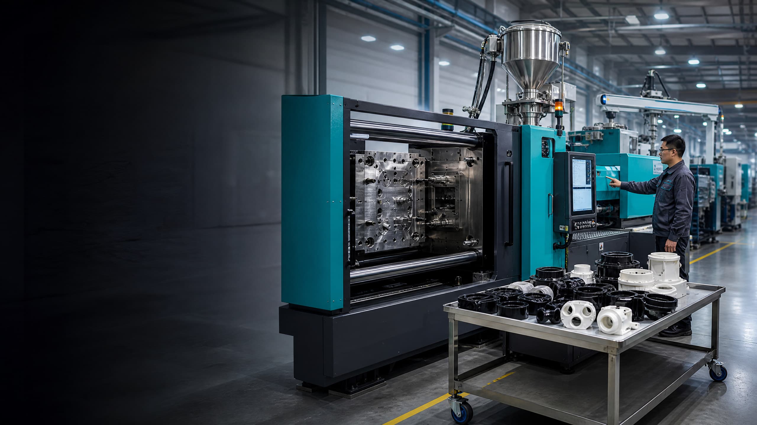
A typical curve rises as polymer reaches the sensor and the cavity fills, changes around velocity-to-pressure transfer, reaches a peak during packing, then falls as the gate freezes and the part cools. Suppliers may monitor arrival time, pressure at transfer, peak pressure, pressure at a defined time, curve area, or the overall curve shape. The meaningful features depend on the part and validation objective; no universal target curve or limit is appropriate for every resin and tool.
At the mold, the signal can show changes not evident in a press setting, including filling, packing, flow-path, venting, cooling, or material variation. RJG lists shorts, dimensions, sink, flash, and warp as issues pressure data can help investigate [3]. It is diagnostic evidence, not a one-to-one defect prediction; verify suspected relationships with retained parts and appropriate checks.
Pressure is also local. One sensor reports conditions at its location, not every surface or every cavity. A curve can remain inside its alert limits while an unmeasured feature, a later-filled cavity, an insert interface, or a cosmetic zone has a problem. Academic review literature likewise notes the demanding temperature, pressure, abrasive, and installation environment for in-mold measurement [2]. Treat sensor condition and installation as part of the measurement system.
02
Choose monitoring scope from product risk, not from a generic equipment list
Cavity-pressure instrumentation is most persuasive where a process excursion could affect a defined CTQ, slow or destructive inspection cannot cover every shot, or stronger lot traceability is needed. Examples include multi-cavity tools, parts with mass- or seal-related concerns, difficult-to-inspect internal geometry, or a documented process-validation requirement. It may be less justified for a simple, low-risk part when routine inspection addresses the agreed risks. The decision should follow the quality plan and risk assessment, not a blanket rule.
Ask for a sensor map before approving the tool. The map should identify direct, indirect, or contact-free measurement; cavity number; distance or relationship to gate and end-of-fill; and any surface or ejection constraints. Direct sensors contact the melt; indirect solutions may measure force through a pin; contact-free arrangements can help where a visible sensor mark is unacceptable. These approaches have different signal behavior and integration constraints [2]. Sensor location should be near the phenomenon being monitored and, for a pressure-based switchover application, in an area where the machine can still influence filling [4].
For a multi-cavity mold, clarify whether every cavity is measured, selected cavities are monitored, or one representative cavity is used. A representative sensor can be useful, but it should not be presented as proof of cavity-to-cavity equivalence. Request the rationale for the selected locations and the method used to investigate a cavity-specific issue.
| Buyer question | Why it matters | Useful evidence |
|---|---|---|
| Which feature or failure mode is monitored? | Prevents a generic data-collection claim. | CTQ list linked to sensor location and inspection method. |
| Which cavities and pressure locations are covered? | Defines what the system can actually observe. | Tool drawing or sensor map with channel identification. |
| What determines an abnormal shot? | Shows whether limits reflect approved-part evidence. | Baseline study, curve limits, and change-control record. |
| What happens after an alarm? | Distinguishes monitoring from effective containment. | Segregation, review, restart, and traceability procedure. |
03
What process-monitoring evidence should be requested before and during production
Before routine production, request a protocol naming the molded part and tool revision, relevant resin condition, machine and hot-runner configuration, sensor channels, sampling period, and monitored curve features. It should explain how a normal range was established using parts that passed agreed inspection and functional tests, and who can revise the reference curve or limits.
During production, an injection molding quality report can show cycle count, accepted and held shots, alarms, operator actions, and a data-retention reference. Buyer and supplier can agree format, frequency, retention, confidentiality, and access. Records should connect to the production lot, tool revision, material lot where practical, and exception disposition.
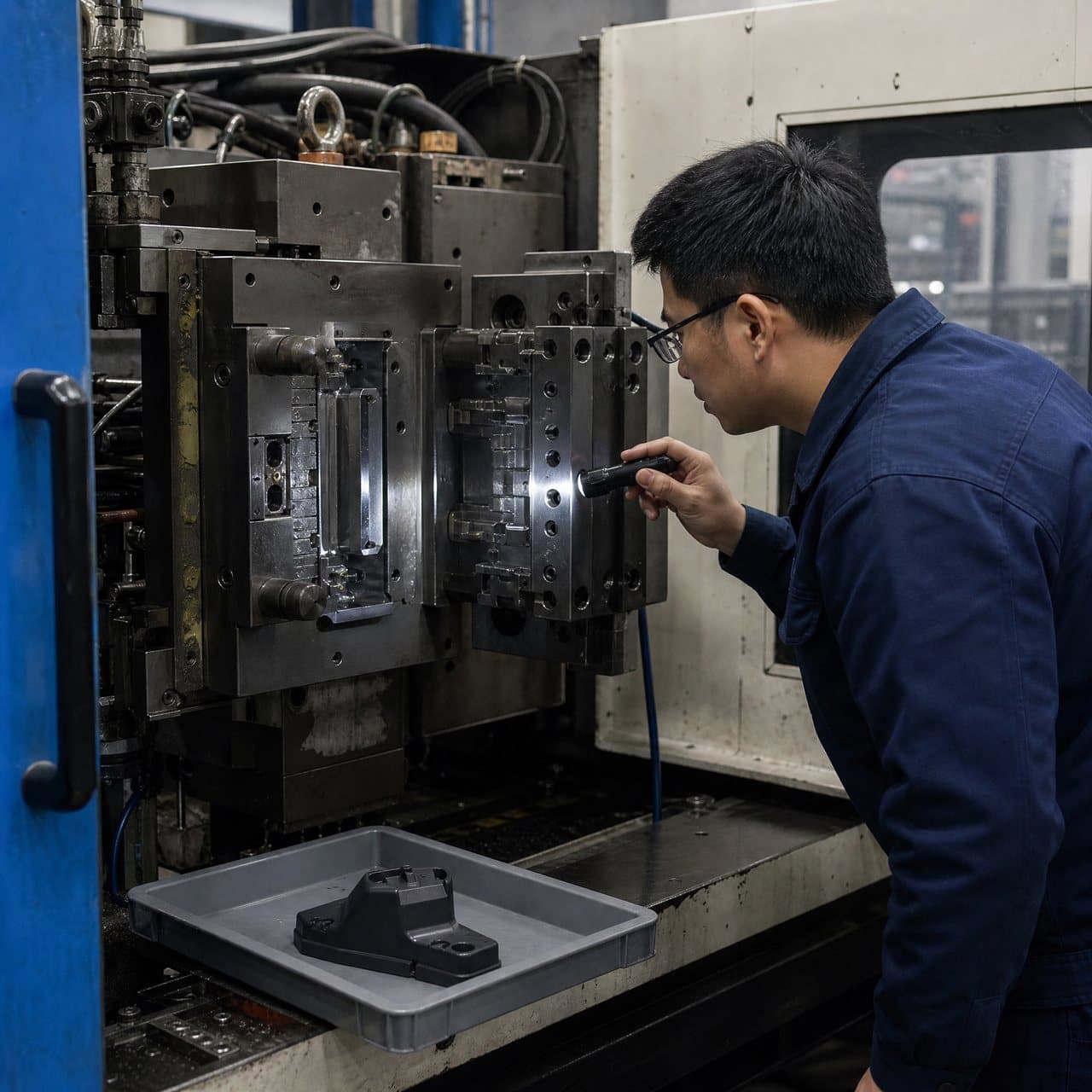
Ask how the system is checked before use and after mold maintenance, sensor replacement, tool modification, or transfer to another press. A damaged, overloaded, or incorrectly installed sensor can create misleading assurance. Kistler lists permanent archiving and data-management interfaces as part of process-monitoring systems [5], but data availability does not replace defined review responsibility. Agree who examines trends, who may release held product, and which events trigger added inspection or engineering review.
04
Use the signal for controlled response, not automatic overclaiming
A sound response plan separates detection from disposition. If a curve falls outside an approved boundary, the system may flag the shot or stop the machine under the validated strategy. The supplier should identify affected product, check the cause, inspect or test as required, document the decision, and establish a controlled restart. An alarm does not establish that every prior or later part is defective, and an in-limit curve does not prove every part conforms.
Pressure data is most useful when read with other process evidence. Compare it with fill time, transfer position, cushion, melt and mold temperatures, cooling time, hot-runner status, part weight where suitable, and the agreed inspection results. If variation appears, avoid changing several settings at once. Record the observed change, investigate likely causes such as material, machine, mold, or environmental conditions, and verify any correction against approved criteria. This makes injection molding defect analysis more repeatable across supplier teams and time zones.
For buyers in Europe, North America, and the Middle East, the practical deliverable is an auditable, mutually understandable decision trail rather than a promise of zero defects. Specify the evidence in the purchase order, quality agreement, or validation plan. Keep the acceptance standard part-specific, and retain independent checks for dimensions, appearance, assembly, and function at the frequency justified by risk.

Practical takeaway
Before you move
to the next review.
- Define the CTQs or failure modes that cavity-pressure monitoring is expected to support; do not request sensors as a generic quality feature.
- Review a sensor map that states measurement method, location, cavity coverage, gate or end-of-fill relationship, and surface constraints.
- Request baseline evidence linking the normal pressure signature to approved parts, with limits controlled by documented change approval.
- Agree alarm containment, product segregation, investigation, restart authorization, and the inspection or test needed for disposition.
- Set expectations for data traceability, review frequency, retention, access, and checks after maintenance, sensor work, material changes, or tool revisions.
FAQ
Common questions
Is cavity pressure the same as injection pressure shown on the machine?
No. The machine display generally reflects a pressure in the injection unit or hydraulic system, while cavity pressure is measured in or through the mold near the formed part. Both can be useful, but they are not interchangeable and should not be expected to have the same value or curve shape.
Does a cavity-pressure system eliminate final inspection?
No. It can help identify process departures in real time and support shot-level traceability. It does not directly verify every dimension, cosmetic requirement, material property, assembly condition, or functional requirement. Inspection and test should remain proportionate to the approved control plan and product risk.
How many sensors does a multi-cavity mold need?
There is no universal number. The answer depends on cavity count, runner balance, CTQs, part geometry, expected failure modes, access, and the intended control decision. Ask the supplier to document the coverage rationale and any limitations of representative-cavity monitoring.
Can a supplier use cavity pressure to reject parts automatically?
Potentially, if the release logic, limits, sensor performance, containment workflow, and relationship to approved parts have been validated for that program. Buyers should request the exception-handling procedure and not treat an automated decision as a substitute for the agreed validation and audit process.
References
Source material
- [1] Kistler: Cavity pressure
- [2] Ageyeva, Horvath and Kovacs, In-Mold Sensors for Injection Molding: On the Way to Industry 4.0, Sensors (2019)
- [3] RJG: Injection Molding Sensor Technology
- [4] RJG: Choosing a Sensor
- [5] Kistler: Monitoring and Control of Injection Molding Processes
This guide is general information for early procurement and engineering discussion. It does not replace product-specific DFM, qualification, validation, regulatory assessment or legal advice.