
Buyers should require every injection mold cooling circuit to be identified, pressure-tested for leakage, flow-tested for restriction, and documented before shipment and again when the tool is commissioned. A pass statement alone is not enough. The useful acceptance record links each circuit to its inlet and outlet, test medium, test pressure, hold time, flow, pressure loss, temperature condition, instrument status, and disposition. This gives purchasing and engineering teams a baseline for injection mold inspection, injection mold validation, future maintenance, and problem-solving if cycle time, warpage, or cavity balance changes. Set project-specific limits with the molder and toolmaker; do not copy generic pressure or flow values into a purchase order without considering the tool, resin, temperature-control unit, hoses, and production machine.
Short answer: specify a circuit-by-circuit air and water integrity test plus a controlled water-flow and pressure-loss test, then require the signed raw results as the cooling-system baseline. The production trial must confirm that the tested circuit arrangement supports stable part quality; a bench test does not prove the final molding process by itself.
01
Define the test objective before the mold is built
A cooling circuit is a heat-transfer system, not simply a set of drilled water lines. It affects cooling uniformity, cycle time, dimensional stability, and appearance. Plastics Technology notes that water-side heat removal depends on coolant temperature change and flow rate, as well as circuit geometry and heat input (Reference 3). Specify both integrity evidence and the injection mold cooling design intent.
Start with a controlled cooling map showing every circuit ID, inlet, outlet, core or cavity location, series or parallel relationship, baffle, plug, seal, manifold, and conformal section. Require the drawing revision used for testing. Without it, a flow report cannot prove which path was measured after assembly changes.
Separate three questions: is the circuit sealed; is its intended path open and unrestricted; and does the production trial support agreed part performance? Bench testing answers the first two. Trial evidence addresses the third.

02
Specify a circuit-by-circuit leak test, not a visual check
Test one isolated circuit at a time, with unused ports sealed and the circuit number on the report. Record medium, supplied pressure, stabilization and hold time, start and end pressure, permitted loss, operator, date, instrument ID, and calibration or verification status. Photographs can support, but not replace, measured results.
A practical sequence is a pneumatic hold test followed, where suitable and safe, by a water hold test. DME describes monitoring air-pressure loss before repeating the integrity check with water (Reference 2). This is more meaningful than observing water at an outlet. Project-specific pressure, duration, and allowable loss must stay within component, seal, and safety limits.
Define escalation: pressure decay beyond the limit, visible leakage, cross-connection, or repeat failure is a nonconformance. Require defect location, repair, re-test circuit ID, and revised result. For export programs, name the report language, units, and conversion convention in the RFQ.
| Evidence item | Example recording method | Buyer acceptance question |
|---|---|---|
| Pressure-hold integrity | Example only: record specified air or water pressure, programmed hold duration, start/end readings, and allowable decay | Was each labeled circuit tested independently and within the project limit? |
| Flow and restriction | Example only: measure water flow at a stated supply pressure and record supply/return pressure or pressure loss | Is there a baseline for each circuit, including parallel paths? |
| Circuit identity | Cooling drawing revision, circuit ID, ports, test date, mold serial or asset ID | Can the raw data be traced to the delivered configuration? |
| Re-test after repair | Nonconformance number, repair description, new test record, approver | Did the repaired circuit pass the same defined test method? |
| Trial correlation | Trial parameters, mold-temperature settings, cavity/part results, noted hot spots or variation | Does production-representative evidence support the cooling design intent? |
03
Add flow and pressure-loss data to prove usable cooling paths
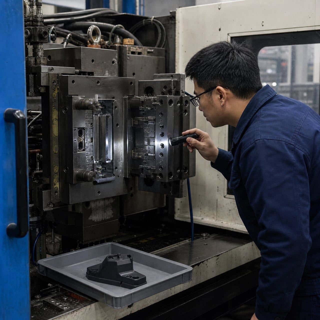
A leak-free line can still cool poorly. Scale, swarf, wrong plugs, blocked baffles, or partial obstruction may reduce heat transfer. MoldMaking Technology notes that tightness and flow-rate tests can identify leakage and strangulation in cooling channels (Reference 1). Require measured flow for every circuit as the new-tool baseline.
Make readings comparable: state the water source or test rig, supply-temperature range, supply pressure or pump setting, hose size where material, and whether the circuit is isolated or manifold-connected. Report L/min and bar or gal/min and psi as measured. Pressure loss has value only beside the flow and conditions that produced it.
For multi-cavity tools, do not average all circuits into one total. Identify cavity groups, core and cavity halves, sliders, cooled hot-runner plates, and independent paths. For a conformal cooling mold, request the released cooling CAD or drawing, port map, and the same circuit-by-circuit empirical records.
04
Turn the bench result into injection mold validation evidence
Make cooling testing a gate before shipment or final tool acceptance, then an input to the injection mold trial. At T0, T1, or another agreed stage, record the machine, resin grade and condition, coolant settings, cycle setting, cavity identity, and relevant dimensional, visual, and functional results. A bench result alone cannot guarantee cycle time.
Compare trial outcomes with the cooling map. If a cavity or feature repeatedly shows warp, sink, incomplete packing, or an abnormal temperature pattern, inspect its circuit before changing multiple process variables. The aim is a traceable chain from design intent, to verified circuit condition, to part performance.
Request portable acceptance evidence: native PDF records, available machine exports, drawing and report revisions, named units, and signatures or electronic approvers. Keep the baseline in the maintenance file and repeat comparable tests after repair, modification, refurbishment, or transfer.
05
Write limits that are project-specific and auditable
Do not write only ‘no water leakage’ or ‘adequate cooling.’ State pass/fail logic in the RFQ, quality agreement, or acceptance plan. If limits are not known, ask the supplier to propose test conditions and acceptance limits at design review, then obtain approval before testing. Never copy illustrative values from another mold into a contract.
Example format only: a stated pressure hold and permissible loss; a minimum flow or maximum pressure-loss range at a stated water condition; and re-testing after cooling-system repair. Confirm all numbers, media, and safety controls for the actual tool. Specify temperature-control connections and receiving-plant interfaces so the test configuration can be reproduced.
Assign ownership: the toolmaker supplies mapped, signed records; the molder confirms installation compatibility and trial correlation; the buyer approves against the plan. Send your part drawing, resin, cavity plan, machine interface, and target acceptance stage for an inquiry on a project-specific cooling-test requirement.

Practical takeaway
Before you move
to the next review.
- Attach the released cooling drawing revision with every circuit ID, port map, core/cavity location, plugs, baffles, and conformal sections identified.
- Require individual circuit air and water integrity records that state medium, pressure, stabilization and hold times, start/end readings, allowable loss, date, operator, and instrument status.
- Require flow and pressure or pressure-loss readings for each circuit under stated water temperature, supply condition, connection, and unit system.
- Define pass/fail limits, re-test rules, and corrective-action documentation before mold assembly; all values must be confirmed for the actual project.
- Link the bench-test report to mold serial or asset ID, drawing revision, and final as-built configuration before shipment or acceptance.
- During the injection mold trial, record coolant settings alongside resin, process settings, cavity-specific part results, and any cooling-related observations.
- Store the accepted results as a maintenance baseline and require comparable re-testing after repair, modification, corrosion cleaning, or tool transfer.
FAQ
Common questions
What is the minimum evidence a buyer should request for a mold water-leak test?
Request a circuit-by-circuit signed record, not only a pass statement. It should show circuit ID, test medium, pressure, stabilization and hold time, start/end readings, permitted loss, result, date, operator, instrument status, and the cooling drawing revision. Any repair should have its own nonconformance and re-test record.
Can an air pressure test replace a water-flow test?
No. An air hold test is useful for detecting loss of circuit integrity, but it does not establish water flow or pressure loss under a defined water condition. Specify both integrity and hydraulic evidence. The agreed test conditions and limits must suit the mold and its components.
How should a conformal cooling mold be tested?
Use the same traceable circuit-by-circuit integrity and flow approach, then add the released cooling CAD or drawing, port map, and trial correlation. Because internal conformal paths can be complex, the buyer should make circuit identification, test configuration, and post-repair re-testing especially explicit.
References
Source material
- [1] MoldMaking Technology — How to Quickly Check Cooling Channels
- [2] DME — CoolingCare: Pressure/Leak Test and Cooling-Channel Diagnostics
- [3] Plastics Technology — Improve the Cooling Performance of Your Molds
This guide is general information for early procurement and engineering discussion. It does not replace product-specific DFM, qualification, validation, regulatory assessment or legal advice.