
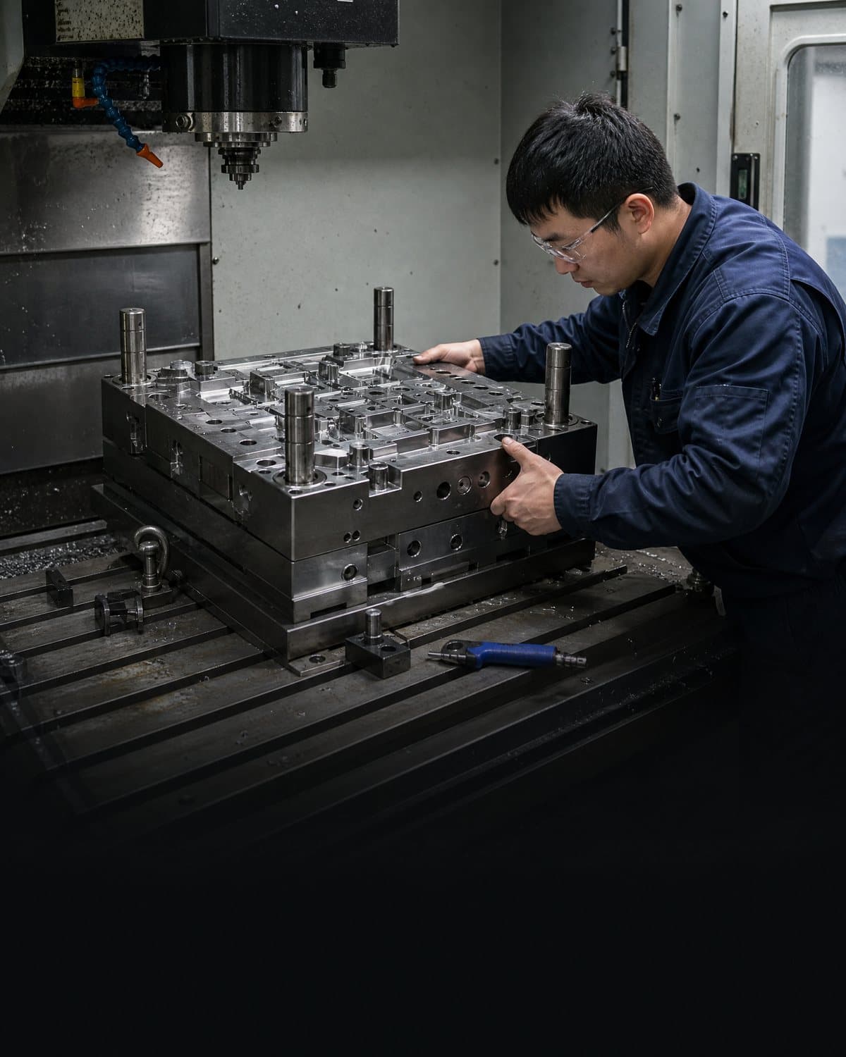
An injection mold guide pin and injection mold guide bushing help guide the moving and fixed halves of a mold into their intended relationship during closing. For a buyer, the decision is less about selecting a catalogue part in isolation than defining the alignment duty that the complete injection mold assembly must meet. Part geometry, cavity layout, tool mass, resin and processing temperature, cycle demand, side actions, required service life and the production press can all change the appropriate arrangement. DME likewise identifies part shape, part tolerance, resin and processing temperature, mold size and type, and mold life among the factors in alignment-system selection [1].
This guide is aimed at an RFQ, design review or pre-acceptance gate. It does not prescribe one universal pin diameter, bushing style, clearance or material. Those choices must be confirmed by the tool supplier against the released design, component standard and application. The buyer’s role is to make the operating assumptions, risks, inspection scope and decision authority explicit—especially when a mold will be trialed by one party and run by another in Europe, the US or the Middle East.
A guide system supports repeatable mold-half guidance; it should not be assumed to provide every precision-locating, load-bearing or safety function. Ask the supplier to identify any separate taper locks, interlocks, support features or safeguarding assumptions needed for the specific tool.
01
1. Define the alignment duty before naming a component series
Start the RFQ with the mold’s job, not a request for ‘standard guide pins.’ State the part and tool revision, cavity layout, mold-base size and moving-half mass where available, production volume, resin family, processing-temperature range and intended press envelope. Identify alignment-sensitive features such as deep cores, thin shutoffs, side actions, large ejection plates, hot-runner hardware or interchangeable inserts. These inputs let a precision injection mold maker assess the guide system as part of the mold architecture rather than as a purchased afterthought.
Describe what must remain aligned and when. A leader-pin arrangement may guide plates during closing, while a critical shutoff or heavily loaded slide may need separate locating or support features. Do not infer that a guide pin alone protects a fine shutoff or establishes every final position. Ask the supplier to mark the proposed load path and alignment sequence on the mold layout, and state which feature controls final cavity/core registration. This matters for multi-cavity and family tools, where a local mismatch can create cavity-specific defects.
| Buyer input | Why it matters | Supplier confirmation to request |
|---|---|---|
| Tool size, moving-half mass, opening orientation and cycle demand | These affect the operating duty and potential wear of the guide arrangement. | Proposed guide-pin/bushing arrangement, position and any design limitations. |
| Cavity layout, long cores, thin shutoffs, side actions and ejection concept | Local loads or sensitive interfaces may need functions beyond general plate guidance. | Which features provide final location, support or anti-rotation, and why. |
| Material, process-temperature range and intended production environment | Heat, contamination and lubrication restrictions can affect fit and maintenance planning. | Compatible component type, surface treatment or lubrication approach, if applicable. |

02
2. Convert alignment intent into controlled design inputs
Ask for a controlled mold drawing or 3D review that identifies each guide position, component designation, standard system or manufacturer, nominal size, engagement length, retained plate and bushing plate. If a non-standard component is proposed, request its drawing and replacement availability. This distinguishes a guide pin, locating element and dowel: suppliers can use these terms differently, and a same-diameter substitute may not offer the same engagement, retention or service behavior. The buyer need not dictate a tolerance stack, but should require the supplier to identify intended fits and their governing drawing or standard.
Specify conditions that can invalidate an otherwise reasonable selection: plate material and thickness, entry-zone wear protection, thermal movement, removal access, lubricant restrictions and contamination control. State whether corrosive, filled, flame-retarded or recycled resin is expected where relevant, but do not assume resin alone determines guide-component material. Where an injection mold tolerance is tight, keep part requirements separate from component fits. ISO 20457 addresses molded plastic-part tolerances and acceptance conditions, not a universal guide-component-fit recipe [2].
For global programs, identify the preferred standard family, metric or inch interfaces where needed, and local spare-part route. A named catalogue standard may improve replacement speed, but it does not remove the need to confirm plate machining, bushing retention and interchangeability in the released injection mold assembly. Require written approval before substituting a component family, coating, lubrication condition or guide layout after design freeze.
03
3. Set acceptance evidence around fit, motion and traceability
Acceptance evidence should prove the agreed configuration and observable behavior, rather than imply lifetime capability from a photograph. Before trial, request a component list tied to the tool ID and revision, the issued assembly drawing, and records for critical non-standard guide elements. Depending on the program, useful evidence includes a supplier fit-check record for nominated features, contractual component traceability, installation photographs, and a declaration of lubricant or assembly condition. A certificate alone does not prove correct installation or intended plate motion.
During bench review, ask the supplier to demonstrate the intended opening and closing sequence at a controlled pace, with ejection and relevant slides or special mechanisms. Look for the agreed engagement sequence, unobstructed movement, labels and no visible contact inconsistent with the design. The exact check method, force, speed and acceptance limit are tool-specific; the supplier should propose them. A dry or low-speed check is useful assembly evidence, but cannot prove production-rate dimensional, cosmetic or wear performance.
Make the report decision-ready. Each exception should identify the tool and component position, finding, evidence, containment, owner, due date and required re-check. If the tool will be shipped before a production-representative trial, state precisely what has and has not been demonstrated. For a critical application, the buyer and responsible engineering team should also define whether independent inspection, a measurement-system review or a later endurance run is required.
| Acceptance evidence | Decision it supports | What it does not prove |
|---|---|---|
| Controlled BOM, assembly drawing and guide-element identification | The reviewed tool uses the agreed configuration and components. | Actual fit, motion or durability under production conditions. |
| Supplier fit or dimensional check for agreed critical locations | The nominated build features were checked against the stated basis. | Conformance of unmeasured features or molded-part capability. |
| Recorded controlled-motion review and exception log | The documented sequence operated in the reviewed assembly state. | Cycle-time capability, wear life, machine safety validation or final part approval. |
04
4. Agree wear response, transfer readiness and safety boundaries
A buying specification should say what happens when a guide system no longer meets the agreed condition. Ask the supplier to propose inspection points or symptoms that warrant review—such as abnormal closing feel, scoring, debris, recurring flash near a sensitive interface or a change in mold-half alignment—and define the escalation route. Avoid an unsupported universal replacement interval: wear depends on design, cycle count, load, lubrication, environment, maintenance history and damage events. Name the inspection owner, record location, repair authority and evidence needed after replacement or rework.
For tool transfer, include guide pins, guide bushings, component drawings, approved substitutions, spare quantities, assembly instructions and open wear findings in the handover package. Confirm that the receiving molder has compatible lifting, clamping, maintenance and cleaning practices; a correct specification cannot compensate for incompatible installation or unsafe handling. If a repair changes a guide position, plate bore, location feature or closing behavior, ask the supplier to confirm renewed bench checks and molded-part evidence before normal release.
Finally, keep alignment and machine safety as related but separate decisions. ISO 12100 provides principles for machinery risk assessment and risk reduction [3]; it does not certify a particular guide arrangement for a buyer’s press, guarding or operating procedure. The responsible parties should confirm safe installation, maintenance access, lockout and mold-area safeguarding under the applicable machine, site and regulatory requirements.
Practical takeaway
Before you move
to the next review.
- Define the alignment duty with part, tool, cavity, resin, machine, production-volume and motion-system inputs before asking for a component size or catalogue series.
- Require the supplier to show what guides plate motion, what establishes final precision location, and what supports sensitive cores, shutoffs or moving mechanisms.
- Freeze component IDs, applicable standard or drawing, plate interfaces, installation locations, service access and change-control rules in the released tool package.
- Approve evidence that links the actual tool configuration to focused fit checks, a controlled-motion review and a traceable exception log; do not treat this as proof of production life.
- Agree wear escalation, spare-part responsibility, transfer records, repair authority and the requalification scope before the mold enters routine production.
FAQ
Common questions
Should a buyer specify the exact injection mold guide pin diameter?
Usually specify the alignment duty and design inputs first, then ask the supplier to propose the size, arrangement and component series with a drawing-based rationale. An exact size can be appropriate when it is part of an approved mold standard, but the supplier should still confirm plate construction, engagement, loads, service access and compatibility with the complete tool.
Are guide pins and guide bushings enough for tight molded-part tolerances?
Not necessarily. They support guided mold closing, but tight molded-part requirements may also depend on cavity and core design, final locating features, tool rigidity, material behavior, process control and measurement method. Ask the supplier which design features control final registration and what molded-part evidence is required for the specific tolerance.
What should be checked after a guide bushing is replaced?
The supplier should confirm the approved component, position, installation condition and the focused checks needed for the affected tool. Depending on the change and risk, that may include a controlled motion review, inspection of nearby interfaces and targeted molded-part checks. Do not assume an identical-looking replacement needs no documented release.
References
Source material
- [1] DME, “Mold Alignment Pins,” overview of leader pins, bushings and alignment-system selection factors.
- [2] International Organization for Standardization, ISO 20457:2018, “Plastics moulded parts — Tolerances and acceptance conditions” (withdrawn; ISO links to the current edition).
- [3] International Organization for Standardization, ISO 12100:2010, “Safety of machinery — General principles for design — Risk assessment and risk reduction.”
- [4] National Institute of Standards and Technology, “Gauge R & R studies,” measurement-system considerations for gauges and instruments.
This guide is general information for early procurement and engineering discussion. It does not replace product-specific DFM, qualification, validation, regulatory assessment or legal advice.