
Review wall map, release direction and assembly features together. A thickened boss can affect a cosmetic wall; a rib can need draft; and a snap may require a different tool split. Suppliers can be compared fairly only when they respond to the same geometry, material direction, appearance restrictions and acceptance priorities.
Ask for a marked-up geometry review that states the proposed change, the reason for it, the affected functional or cosmetic surface, and the buyer decision still required. A generic green-light on a model is weaker evidence than a visible trade-off record.
01
What should be decided together before a supplier quotes?
Start with the part’s job, not a rule copied from another resin or programme. Identify the surfaces that locate, seal, receive a screw, carry load, flex, remain visible, or must be free of gate, ejector or parting-line evidence. Then choose the likely mold-opening direction and mark where draft consumes clearance or changes an outside envelope. This gives engineering and procurement one decision map instead of several disconnected comments on CAD.
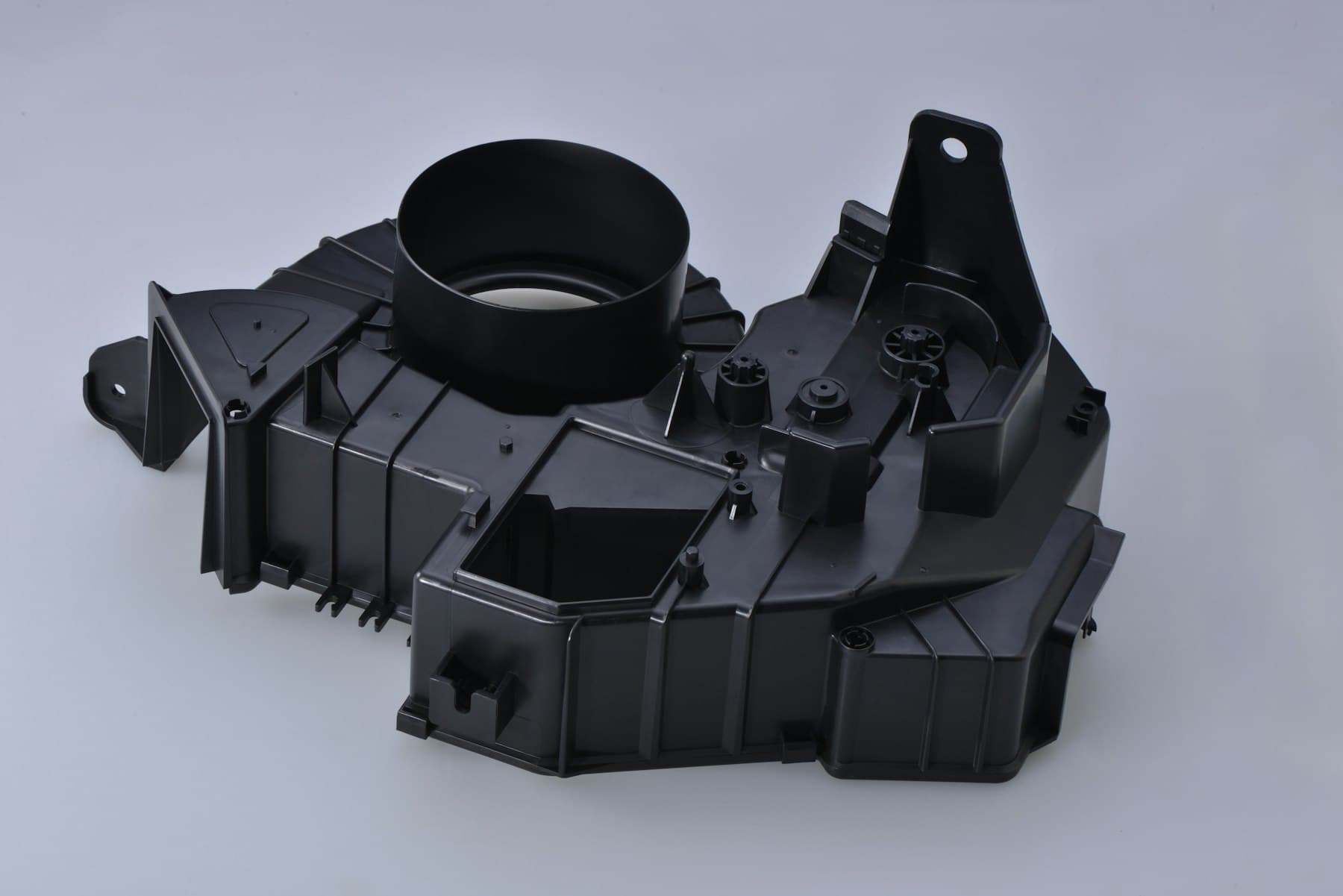
The most useful RFQ comparison asks each supplier to identify assumptions rather than to certify a design. Provide the controlled model and drawing, preferred material or material-selection route, expected assembly sequence, mating components where relevant, annual-demand scenario, and visual restrictions. Ask the supplier to show nominal walls, local thick zones, tool-pull direction, draft-sensitive faces, likely gate and ejection areas, and any feature requiring side action or a change in assembly concept. A response that makes these assumptions visible is more comparable than one that only names a tool type or total price.
02
How should buyers review injection mold wall thickness before adding features?
An injection mold wall thickness review should begin with a nominal section selected for the actual material, flow distance, load, finish and part size. It is not a search for one universal millimetre value. Plot the wall condition in section views and look for abrupt changes, closed-off pockets, thick intersections, sharp internal corners and long unsupported spans. Where a local thickness change is necessary, ask whether a smoother transition, coring, a radius or a different structural layout would preserve the product requirement with less local mass.
This wall map becomes the reference for every later feature. A rib, boss or snap root that adds material on one side of a cosmetic face may create a different cooling and shrinkage condition than the surrounding wall. Published guidance commonly treats secondary feature roots in relation to the adjacent nominal wall as a starting point, often in a 40 to 60 percent range, but that is not a release criterion. The applicable resin grade, local geometry, gate route, visible surface and the supplier’s detailed design review still determine whether an alternative is appropriate.
| Wall-map condition | Buyer question | Practical next step |
|---|---|---|
| Thick local block | Is this mass needed for function, or could the volume be cored while retaining the load path? | Request a section comparison that shows the proposed core, radii and adjacent supporting ribs. |
| Abrupt transition | Does the transition create a cosmetic, dimensional or stress-sensitive area near a critical interface? | Request a blended or radiused alternative and assess it against the mating geometry. |
| Cosmetic surface behind a feature | What local thickness is visible from the show face, and what evidence will judge the result? | Mark the surface on CAD and agree the visual reference or review condition before trial. |
03
How does injection mold draft angle change the structural plan?
Injection mold draft angle is the taper on faces that follow the opening direction. It should be reviewed at the same time as the wall map because adding taper alters internal clearance, outer dimensions, rib depth, boss geometry and snap engagement. A draft value that looks small in one shallow area may materially affect a long wall, a deep pocket or a controlled assembly interface. Texture, finish, resin shrinkage and ejection strategy can further change the practical requirement, so a generic degree value is a starting conversation rather than a contractual outcome.
Ask suppliers to display both the proposed pull direction and the resulting drafted geometry. For an enclosure, inner and outer walls may need to remain appropriately related so the design does not create an unnecessarily difficult deep steel feature. For a rib or boss, the team should see whether the draft is applied on the feature, the surrounding wall, or both, and whether it changes screw access, clearance or a critical datum. If a vertical functional surface cannot accept draft, the review should identify the consequence and compare feasible alternatives instead of silently leaving a zero-draft condition in the model.

04
When do injection mold ribs and injection mold bosses improve the design?
Injection mold ribs can be an efficient way to increase stiffness without making an entire panel thicker, but they are not independent fins added after the wall decision. Review their root thickness, height, spacing, base radius, draft and termination together with the wall on the opposite side. A rib may be structurally useful while still placing a local thickness concentration behind a visible face. Where a rib must carry a load or connect to a boss, ask for a section that shows the full load path rather than only a top view of the feature.
Injection mold bosses should likewise be treated as attachment systems, not cylinders placed wherever a screw is convenient. The review should identify the screw, insert or locating function; the allowable assembly force and access; the core or hole formation; the adjacent wall; and the gussets or links that transmit load. Keeping a boss isolated from a main wall or supporting it with appropriately considered ribs can reduce a concentrated mass, but neither layout proves assembly strength. Product teams should decide how the finished joint will be evaluated and whether the material, fastener, insertion route and service environment need a separate validation plan.
| Design objective | Prefer to compare | Do not assume |
|---|---|---|
| Increase panel stiffness | A ribbed or gusseted layout versus a thicker panel, with the same functional boundary conditions. | That a thicker wall is automatically stronger, more stable or easier to mold. |
| Support a fastening point | A boss with a deliberate connection and load path versus a boss merged into a wall. | That a nominal boss diameter alone establishes joint performance. |
| Protect a visible face | Feature placement, coring and root geometry options shown from the cosmetic side. | That an unseen interior feature cannot affect an exterior appearance. |
05
How should injection mold snap fit and injection mold living hinge decisions be separated?
An injection mold snap fit is generally a retention feature that deflects during assembly and then returns to engage. Its useful review questions are the permissible deflection, required engagement, assembly direction, expected assembly and disassembly events, contact faces, surrounding clearance and how the undercut will be formed and released. Material behaviour and service conditions matter as much as its outline. A supplier can comment on moldability and propose a tool route, but the buyer should retain the product decision on retention force, allowable assembly effort, rework and the evidence needed to accept the joint.
An injection mold living hinge is a different design problem. It deliberately concentrates repeated flexing in a thin connecting section, often with a material choice and gate orientation selected around that function. It should not be approved simply because a snap has been used elsewhere in the part. Ask whether the hinge must fold flat, how many movements the product requires, what bend direction and assembly state matter, and whether the moulded condition and subsequent handling are relevant to the intended use. Published guidance identifies polypropylene and polyethylene as common candidates, but a polymer family alone does not establish life, stiffness or suitability for a specific product. Keep any use-cycle or performance claim in a part-specific validation plan.
| Feature type | Primary buyer decision | Review evidence before tool release |
|---|---|---|
| Cantilever or annular snap | Retention, assembly effort, access and whether re-opening is required. | Deflection direction, undercut and tool-release concept, mating geometry and proposed functional acceptance method. |
| Snap beside a cosmetic wall | Whether the structural root and tool solution protect the visible surface. | A section through the root, show face and ejection path, with the cosmetic criterion identified. |
| Living hinge | Material route, required movement, bend direction, gate relationship and product-level performance question. | A hinge section, flow and gate proposal, controlled material direction and a named validation owner. |

Practical takeaway
Before you move
to the next review.
- Send the current controlled CAD, drawing, material direction and assembly sequence, and identify what remains open rather than allowing suppliers to infer it.
- Mark nominal walls, local transitions, cosmetic faces, critical interfaces and no-gate, no-ejector or no-parting-line zones in the review pack.
- Request one supplier view that combines pull direction, draft-sensitive faces, ribs, bosses, snaps, hinge areas and any proposed undercut solution.
- Compare quotes only after aligning each supplier’s tool-concept assumptions, geometry changes, included engineering review and sample or inspection scope.
- Record the buyer owner for each unresolved function, appearance, material, assembly and validation decision before authorising detailed tool design.
FAQ
Common questions
Should buyers specify exact rib and boss ratios in the purchase order?
Use published ratios as discussion prompts, not as a stand-alone acceptance specification. The useful purchase input is the controlled part definition, material direction, functional load or assembly question, visible-surface restrictions and the evidence needed for approval. Ask the supplier to explain any proposed root, radius, draft or placement change against those inputs. The final geometry should be approved through the part-specific review rather than selected from a generic ratio alone.
Can a supplier solve an inadequate draft condition after tooling begins?
A supplier may be able to propose a tool or geometry change, but the commercial and technical consequence depends on the affected surface, resin, texture, dimensions, release direction and tool concept. Treat the condition as an open decision before tool release. Request a marked comparison of the present and proposed geometry, the impact on function and appearance, and any effect on the quoted scope. The product owner should approve product-impacting changes.
What proof should a buyer request for a snap-fit or living-hinge feature?
Request evidence that answers the product question rather than a generic statement of capability. For a snap, that may mean an agreed assembly condition, engagement check and rework requirement. For a living hinge, it may mean a controlled material direction, hinge geometry, flex condition and product-level evaluation plan. Define who supplies mating parts or fixtures, who judges the result and what decision the evidence supports. A sample alone does not establish end-use performance.
References
Source material
- [1] Protolabs, Injection Molding Wall Thickness Guidelines
- [2] Protolabs, Draft Angle Guidelines for Injection Molding
- [3] Protolabs, Living Hinge Basics for Injection Molding
- [4] Hubs, Injection Molding Design Guide
This guide is general information for early procurement and engineering discussion. It does not replace product-specific DFM, qualification, validation, regulatory assessment or legal advice.