
An automated molding cell is a coordinated system: the mold must release the part consistently, the press must provide the right sequence and signals, the end-of-arm tool must hold the part without creating damage, and downstream equipment must accept it at the required orientation. If any handoff is vague, the robot can merely transfer uncertainty faster. The buyer’s task is not to prescribe a brand of robot or promise an output rate. It is to turn the product and demand into testable requirements, then compare proposals against the same assumptions.
This guide assumes a conventional thermoplastic molding program in which parts leave a mold and may be separated, inspected, cooled, packed or presented to a secondary process. Insert loading, multi-shot tooling, very high-temperature materials, cleanroom arrangements and regulated products can introduce additional controls. They should be scoped separately with the system integrator and the product owner. Automated injection molding should therefore be released in stages: establish a stable part and tool concept, prove the physical handoffs, assess the safeguarded cell, and accept the combined process against an agreed plan.
Ask a supplier to demonstrate a complete operating scenario, including rejected parts, a missed pick, restart after a stop and changeover. A nominal robot path alone is not production evidence.
01
1. Define the job to be automated before selecting the robot
Start with a cell charter that follows the part from cavity to its first stable downstream location. Name the part revision, resin and colour direction, cavity layout, production pattern, cosmetic zones, critical interfaces, allowable contact faces, handoff orientation, destination and acceptance owner. Include runners, sprues and rejects when they exist. A cell that picks good parts but leaves runner separation, cooling or defect segregation unresolved is not complete.
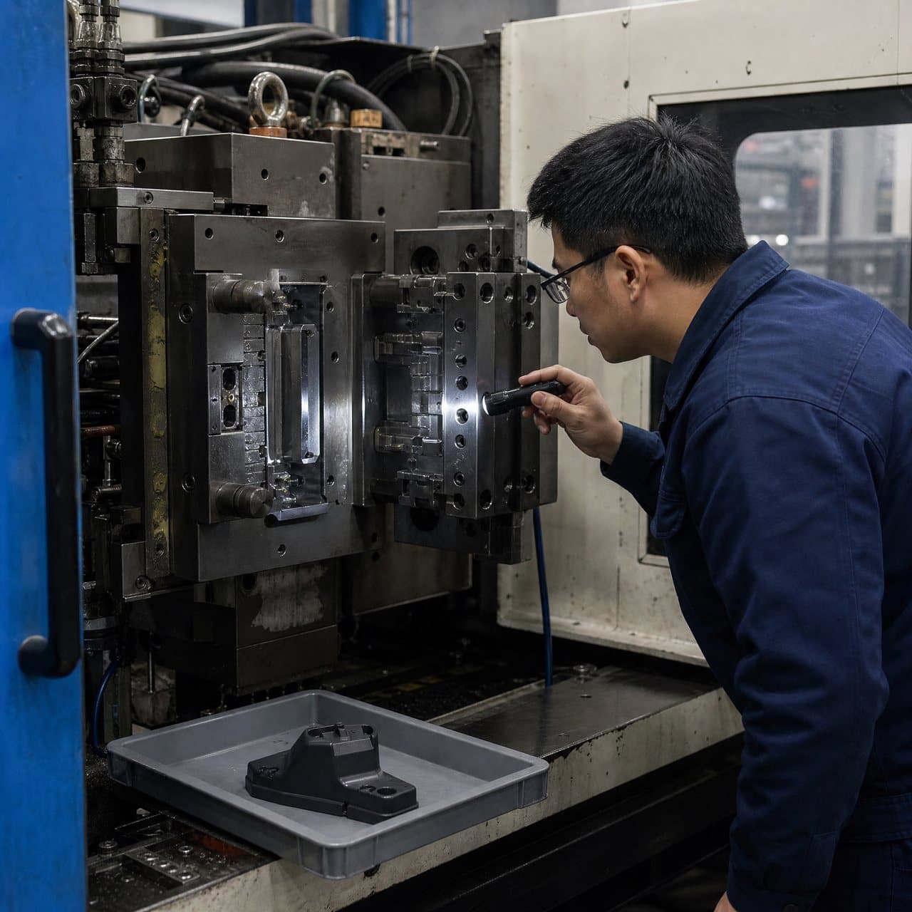
For robotic part handling injection molding, payload is more than part mass: it includes the hot part, any runner, gripper, cups or fingers, hoses and cables, plus acceleration and reach. Thin ribs may flex; glossy surfaces can show cup marks; a deep part may stick on a core; and static charge can affect release. Ask for the proposed end-of-arm tooling, contact points, sensing method, safe drop behavior and service/changeover approach. The proposal should address wrong orientation, double pick, missing part and incomplete release.
Separate required work from possible future work. Mold opening, removal, degating, camera checks, cooling, labeling, assembly and packing have different timing and risk profiles. An initial phase may only require repeatable mold takeout and lot segregation; a later phase may add inspection or packaging. This modular view can prevent a buyer from paying for unproven downstream complexity, while reserving footprint, signals and mechanical interfaces for a future upgrade. It also gives suppliers a clearer basis for identifying which tools, fixtures and controls are inside their scope.
| Handoff | Buyer definition needed | Evidence to request before release |
|---|---|---|
| Mold to gripper | Part and runner state, permitted contact areas, release direction and orientation. | End-of-arm tooling drawing or concept, interference review, pick confirmation and missed-pick response. |
| Gripper to downstream station | Required presentation, cooling condition, queue limit and accepted part identity. | Layout and sequence diagram showing normal flow, reject flow and buffer ownership. |
| Inspection or secondary step | Characteristic to check, decision rule, traceability need and disposition authority. | Test method, sample states, false-reject/escape discussion and manual fallback procedure. |
| Pack-out | Count, orientation, surface protection, lot separation and label information. | Pack-out trial or documented handoff criteria using the agreed packaging concept. |
02
2. Size the cell around the slowest repeatable event, not an ideal demonstration
A capacity discussion should begin with a time budget rather than a claimed parts-per-hour figure. Map mold close, fill, pack/hold, cooling, mold open, ejection, robot entry, pick confirmation, withdrawal, optional runner work, downstream transfer and any wait for a station. Some robot motions can occur while the part cools; others extend the press-open portion of the sequence. The target is not simply the fastest movement. It is a sequence that protects part release, mold clearance, cooling and downstream reliability.
Injection molding cycle time is especially easy to misinterpret when automation is added. Cooling, wall thickness, resin behavior, mold temperature, cooling-circuit performance and ejection condition may dominate the available window. RJG's technical explanation illustrates why cooling is a major portion of a molding cycle and why geometry, material, mold design and processing all matter.[1] A modeled or observed robot motion cannot justify reducing cooling or opening time unless the actual part still releases, holds shape and meets its agreed checks. Treat any preliminary cycle as an engineering assumption to verify at trial, not a contractual guarantee.
Request three scenarios: a planned normal cycle, a conservative start-up or stabilization cycle, and a recoverable disruption case. For each, identify what data are recorded, whether the press waits, how parts are segregated, and who can restart the cell. Compare proposals using the same number of cavities, part mass, material condition, cooling assumptions, downstream tasks, staffing boundary and planned operating schedule. This is more useful than comparing a robot's maximum axis speed or a single best-case video.
| Planning approach | What it can establish | What it cannot establish by itself |
|---|---|---|
| Offline layout and reach study | Clearance envelope, approximate reach, access and tentative sequence. | Actual part release, vacuum grip, sensor reliability, cooling adequacy or real uptime. |
| Dry run without molded parts | Interlocks, motion logic, station access and basic recovery sequence. | Hot-part behavior, cosmetic contact effects, static, shrinkage-related release or production quality. |
| Molded trial at agreed conditions | Combined mold, robot and downstream timing with actual parts and defined checks. | Long-term capability or every future material, tool and product revision. |
| Production observation after release | Whether the accepted controls and recovery rules work under the agreed operating pattern. | Permission to bypass change control when the process or product changes. |
03
3. Treat interfaces, safeguarding and recovery as part of the technical specification
The press, robot, mold, conveyor, inspection equipment and guarding need a declared interface map. Separate safety-related signals from ordinary sequence and data signals. In European equipment ecosystems, EUROMAP 67 describes an electrical interface between an injection molding machine and a handling device or robot; its stated purpose is interchangeability, while it also notes the role of redundant safety channels for handling-device movements.[2] The actual machine, robot and controller versions still need to be checked. Do not assume that a named interface proves compatibility, covers every peripheral, or replaces the integrated cell's engineering review.
Write a cause-and-effect list for normal operation and for abnormal events: emergency stop, guard opening, robot not clear, mold not open, missed pick, gripper fault, rejected part, low buffer, air or vacuum loss, power recovery and controller restart. It should say which equipment stops, whether the mold may close, where uncertain parts go, who may clear a fault, and what confirmation is needed before restart. This turns a vague phrase such as injection molding automation into a controllable operating model. It also helps purchasing identify omissions between the press supplier, mold builder, robot integrator and downstream-equipment provider.
Safety obligations depend on where the cell is installed, who places it on the market and whether an existing system is modified. OSHA's robot guidance says each robot application should have a documented risk assessment before commissioning and describes site acceptance as confirmation with the site's utilities, interfaces and environment.[3] For equipment placed on the EU market, the European Commission states that the current Machinery Directive applies before 20 January 2027 and the Machinery Regulation becomes mandatory on that date.[4] North American and Middle East buyers should likewise have a competent integrator and local responsible parties confirm applicable laws, standards, safeguarding, training and documentation. This guide is a procurement framework, not a legal or safety compliance determination.

04
4. Plan acceptance evidence for the whole cell, including the exceptions
The factory acceptance and site acceptance plans should be written before build completion, even if detailed set-points remain provisional. Link each test to a buyer decision: Does the robot avoid the mold throughout the intended sequence? Does the cell reject or segregate a confirmed nonconforming part? Can an operator access the allowed service point safely? Does a stop preserve product identity? Are the correct drawing, tool, material and software or parameter revisions recorded? State the tester, witness requirement, result format, acceptance rule, deviation path and retest responsibility. A video is useful context but is not a substitute for a defined test record.
Production injection molding needs a baseline for the integrated process, not just approval of a standalone molded sample. At the intended trial state, record the part and mold revisions, material identity, relevant press and mold settings, robot program revision, end-of-arm tool revision, downstream fixture or inspection recipe, and the agreed critical checks. If a later change affects the release direction, cavity arrangement, material, tool, program, gripper or measurement method, assess whether the original evidence remains relevant. The appropriate response may range from document review to a targeted rerun, depending on risk and the buyer's specification.
Automated part handling should also have a graceful manual or controlled-recovery path. Define who can remove a trapped part, how the cell is put into a safe state, how the mold is protected, what is discarded or re-inspected after interruption, and how production resumes without mixing uncertain parts with accepted output. For high-value cosmetic or function-critical components, ask the integrator to demonstrate the agreed recovery cases in the acceptance test. The aim is not to make every fault impossible; it is to keep fault handling visible, safe and traceable.
05
5. Compare proposals as integrated scope, lifecycle support and verified assumptions
A comparable proposal identifies the limits of supply: press interface work, robot and controller, guarding, end-of-arm tooling, conveyors, buffers, inspection, utilities, programming, training, documentation, spares, remote support assumptions, installation, and acceptance activities. Ask which party owns mechanical and electrical integration, risk assessment coordination, layout changes, performance testing and software backup. A low initial scope may be appropriate, but only if exclusions and future interfaces are visible rather than assumed.
Buyers in Europe, North America and the Middle East may differ in plant utilities, site rules, language needs, local service coverage, import responsibilities and electrical conventions. Do not infer suitability from a supplier's brochure. Provide the installation country, site constraints, utility details, preferred documentation language, operator access limitations, local emergency response rules and any customer-mandated standard at RFQ stage. Ask each bidder to list the assumptions it requires the buyer to validate on site.
Finally, treat availability and maintenance as a joint operating plan. A cell can lose useful output through a blocked conveyor, contaminated vacuum cup, worn finger, poor mold release, sensor drift or slow recovery. Request inspection points, changeover tasks, consumable and spare recommendations, diagnostic access, backup/restore procedure and escalation contacts. Review these with the mold maintenance plan. This does not predict output or establish a supplier commitment; it gives the buyer practical questions for testing whether the cell can be operated and maintained as intended.
Practical takeaway
Before you move
to the next review.
- Issue a controlled cell charter showing the complete part path, orientation, contact restrictions, reject route, downstream destination and every scope boundary.
- Request a time-budget model with normal, conservative and disruption scenarios; verify it with actual molded parts rather than a robot-speed claim.
- Obtain an interface and cause-and-effect list covering safety signals, sequence signals, utilities, lost-part response, restart and manual recovery.
- Define factory and site acceptance tests that include a missed pick, reject segregation, safe stop, restart, revision record and relevant part checks.
- Ask each bidder to state country-specific site assumptions, integration responsibilities, required buyer inputs, planned maintenance tasks and excluded scope.
FAQ
Common questions
When does a robot actually shorten a molding cycle?
Only when its required motion fits within the process window without compromising part cooling, mold clearance, ejection, downstream flow or accepted quality. A robot can remove manual wait time or make handoff more repeatable, but its effect must be tested using the actual mold, material, part and sequence. Compare the integrated time budget, not the robot's catalog speed.
Is an EUROMAP interface enough to make a robot and press compatible?
No. It can provide a defined interface for specified functions, but the buyer should still verify the exact press, robot, interface version, signal set, safety architecture, physical clearances, controller logic and downstream equipment. The integrated cell requires application-specific review and acceptance testing.
What should be accepted before automated production starts?
Agree evidence for the part and tool revision, material direction, normal sequence, safe-stop behavior, recovery after selected faults, rejection and segregation route, program and fixture revisions, and the part-specific inspection or functional checks. The scope should be proportionate to the component and local safety responsibilities; it is not a universal approval package.
References
Source material
- [1] RJG, “How to Determine Injection Molding Cooling Time.”
- [2] EUROMAP, “EUROMAP 67: Electrical Interface between Injection Moulding Machine and Handling Device / Robot.”
- [3] U.S. Occupational Safety and Health Administration, “OSHA Technical Manual: Industrial Robots and Robot System Safety.”
- [4] European Commission, “Machinery.”
This guide is general information for early procurement and engineering discussion. It does not replace product-specific DFM, qualification, validation, regulatory assessment or legal advice.