
Core, cavity and shutoff choices are not merely toolmaker details. They influence how a part separates from the tool, where it remains for ejection, which faces seal against molding pressure, and what evidence is useful if a concern appears at trial. For buyers comparing overseas suppliers, the aim is not to prescribe every steel feature. It is to ensure that every proposal is based on the same controlled part revision, material direction, demand assumptions and acceptance priorities.
A useful review turns a black-box concept into a decision record. It shows opening direction and side allocation; identifies parting, shutoff, gate, vent and ejection zones; and separates product requirements from supplier assumptions. This is particularly useful when teams work across time zones, units and drawing conventions.
Approve the decision logic, visible risks and evidence plan—not a blanket promise that one core, cavity or shutoff arrangement suits every resin, finish and production condition.
01
What should a buyer ask before approving the core and cavity split?
Start with the part’s intended mold-opening direction, not with a generic preference for an A-side or B-side. The cavity forms one side of the part and the core forms the opposing or internal geometry. Cooling shrinkage and geometry influence which half retains the part for ejection. Ask the supplier to show the part in the open-mold position and identify the retained side, ejection contacts and features that could hang up or distort. Protolabs uses a cup-like part to demonstrate why a part may be arranged to stay on the core side carrying the ejector system.
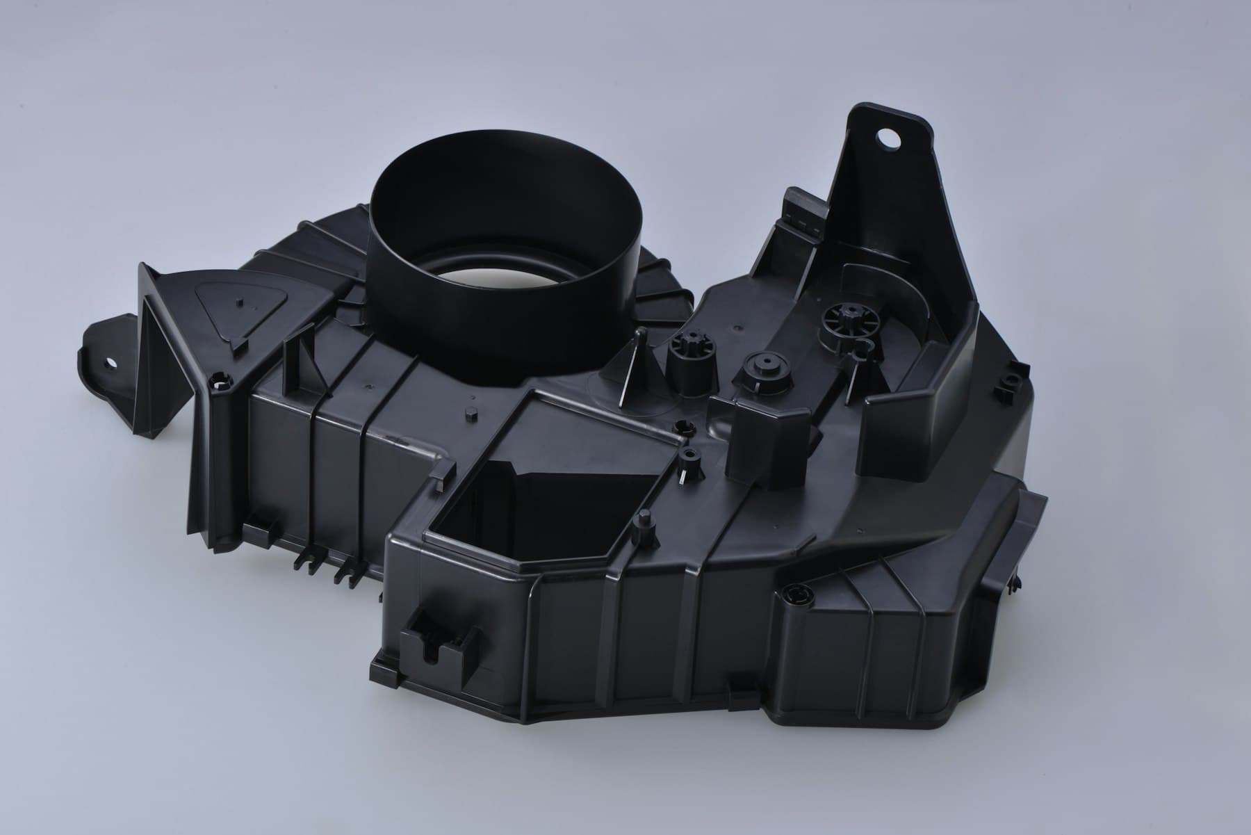
Injection mold core design is more than the internal shape. Review whether the proposed core supports critical internal dimensions, permits the intended draft and gives practical ejection access. Injection mold cavity design deserves the same review for exterior faces, finish boundaries, cooling access and mismatch-sensitive areas. Request a sectioned CAD view that marks draw direction, fixed and moving sides, core and cavity assignment, ejection zones, inserts or actions where relevant, and surfaces connected to critical dimensions.
02
How do parting surface and parting line decisions affect the buying case?
An injection mold parting surface is the three-dimensional interface where tool elements meet; the injection mold parting line is the boundary that may be visible on the molded part. A short visible line can arise from a complex surface, and a simple-looking part can require a discontinuous split. Review whether the proposed interface permits opening, draft, sealing, venting, machining and maintenance without placing tool evidence on a functional or appearance-critical area.
Mark display faces, seal lands, interfaces, datums, tactile edges and areas visible after service. A split acceptable on an underside may be unsuitable if flash interferes with a seal or locator. Moving it only for appearance can shift venting or make a tool interface harder to inspect. Fictiv links parting-line location with draft, flash and tool cost. Treat published draft guidance as a starting point: resin, depth, finish, shrinkage and ejection all affect the practical answer.
| Review item | Evidence to request | Buyer decision before tool release |
|---|---|---|
| Draw and side allocation | Sectioned CAD showing opening direction, retained side and ejection zones. | Confirm that release does not compromise a CTQ, seal, interface or protected face. |
| Parting interface | Marked parting surface and parting-line path on the controlled revision. | Accept, relocate or escalate a path through a sensitive zone. |
| Draft and finish | Marked low-draft faces with resin and texture assumptions. | Decide whether geometry, finish or acceptance priorities need revision. |
| Venting and end of fill | Proposed vent access and likely end-of-fill zones. | Check that a cosmetic request does not silently remove a venting route. |
03
What makes a shutoff proposal reviewable rather than risky?
Injection mold shutoff design concerns mating tool faces that close off a region so melt is contained or a slot, opening or local feature can be formed. Do not approve it from a label alone. Ask what the shutoff forms or protects, whether it is fixed or moving, how it is supported in the closing direction, and which part feature could be affected by wear, damage or incomplete sealing. A compact cross-section is more useful than a claim of “positive shutoff.”
For each consequential shutoff, request the associated part feature, contact direction, draft or relief logic, adjacent venting, inspection access and the likely result of an adjustment. The correct geometry depends on resin, flow, pressure, feature depth and construction; it should not be replaced by a universal angle in a purchasing specification. Eastman’s guidance also supports asking how air leaves the region, where venting can be checked and what trial observation would prompt review.
| Shutoff question | Why procurement should ask | Credible supplier response |
|---|---|---|
| Which part feature does it form or protect? | Links a tool interface to a customer requirement. | Marked section naming the feature and its priority. |
| How is it supported during closing? | Exposes unstated alignment or action assumptions. | Brief explanation of closing direction and dependent components. |
| Where can flash, wear or venting effects appear? | Makes acceptance and maintenance implications visible. | Marked zones, inspection access and trial observations. |
| What changes if correction is needed? | Prevents an unreviewed late scope change. | Affected features, proposed evidence and decision owner. |

04
How should buyers compare suppliers when the core-cavity concepts differ?
Do not select a concept from total tooling price alone. A lower-priced proposal may assume a different cavity count, draw direction, resin, surface finish, inspection method or maintenance scope. Give every finalist the same one-page review brief and request the same minimum evidence: controlled CAD revision, orientation, core/cavity allocation, parting and shutoff locations, gate and vent assumptions, ejection approach, open risks and proposed trial observations.
For injection mold core cavity decisions, separate fixed requirements from tooling alternatives. Fixed items might include an assembly datum, no-ejector zone, seal path or protected visual face. Alternatives might include split route, insert strategy or ejection layout. Require the supplier to state the benefit, drawback and requirement affected for each option. A usable response labels resin and finish assumptions, identifies missing information and distinguishes a preliminary concept from a released design.
05
What evidence closes the review at design release and trial?
Before release, request a concise decision pack recording the selected part revision, material direction, draw direction, core/cavity assignment, parting and shutoff map, gate and vent assumptions, ejection zones, protected surfaces and unresolved risks. Add the commercial boundary: included tooling scope, change authority, requote triggers, and samples or records needed for acceptance. This buyer-facing baseline does not replace detailed supplier tool design.
At trial, inspect the question the concept was meant to answer. Confirm part and tool revision, material identity, cavity or position where applicable, and agreed sample conditions. Review nominated dimensions, assembly or sealing interfaces, designated visual areas, gate and ejector zones, and features formed by critical shutoffs. If an issue appears, ask for containment, the hypothesis, the changed variable and targeted next evidence rather than assigning fault from appearance alone.

Practical takeaway
Before you move
to the next review.
- Issue one controlled CAD and drawing package marking CTQs, seal or assembly interfaces, cosmetic classes, no-ejector zones and units.
- Request a sectioned concept showing draw direction, core and cavity allocation, retention, ejection, parting surface, parting line and consequential shutoffs.
- Have each supplier state the resin, colour, finish, cavity-count, gate, vent and trial assumptions; label unknowns as open.
- Record every alternative, affected part feature, supplier recommendation and buyer decision owner on the same comparison sheet.
- Release tooling only with a decision pack and trial plan covering critical shutoff features, dimensions, interfaces and agreed visual zones.
FAQ
Common questions
Should a buyer tell the supplier exactly which side must be the core or cavity?
Usually, define the part requirements and protected surfaces, then ask the supplier to explain the side allocation. A prescribed side may be justified by an established transfer, assembly or inspection requirement, but it still needs checking against release, ejection, material and geometry. Approve the rationale and impact, not a side label in isolation.
Is a shutoff automatically a quality risk?
No. Shutoffs are normal tool-design features. Risk depends on the specific interface, part feature, material, molding conditions, support, venting and maintenance access. Request a marked concept, intended inspection route and correction path if trial evidence requires change.
What is the most useful document to request before a tooling purchase order?
Request a buyer-facing decision pack: controlled section or annotated CAD, core/cavity and draw-direction logic, parting and shutoff map, ejection, gate and vent assumptions, open risks, change authority and targeted trial evidence. It makes proposals comparable without requiring the buyer to own the detailed tool design.
References
Source material
- [1] Protolabs, How to Choose Core and Cavity Placement in Injection Molding Parts.
- [2] Fictiv, Parting Line Injection Molding.
- [3] Protolabs, Draft Angle Guidelines for Injection Molding.
- [4] Eastman, Processing and Mold Design Guidelines.
This guide is general information for early procurement and engineering discussion. It does not replace product-specific DFM, qualification, validation, regulatory assessment or legal advice.