
A multi-material part is not fully specified because the CAD model shows two colours or two bodies. The buyer must define what each material is intended to do, how the boundary must perform, how the part will be located and ejected, and what evidence will decide whether the result is acceptable. This is especially important when the hard component carries fit or load while a softer component provides grip, sealing, damping or identification. A visually convincing sample can still be a poor basis for release if the grade, bond mode, environmental assumptions or change rules are unclear.
This guide assumes two thermoplastic materials are molded into one finished component. It does not assume that a particular bond, resin pair, tool layout, machine capability or market approval is suitable. Buyers in Europe, North America and the Middle East should state the destination market, actual service exposures and customer-controlled requirements in the RFQ, then verify the proposed grades and validation method with the relevant material supplier, product owner and molder. The purpose is a part-specific specification, not a generic compatibility chart.
Specify the interface as a functional feature with an acceptance method; do not treat it as a decorative line between two resins.
01
Start with the function map, not the process name
Begin by dividing the component into functional zones. For each zone, record its job: structural support, tactile grip, fluid exclusion, electrical isolation, colour identification, abrasion contact or cosmetic cover. Mark which surfaces are customer-visible, which touch a mating part, which are loaded, and which may receive cleaners, oils, sunlight, heat, cold, humidity or repeated flexing. A border that merely locates a soft grip has a different risk profile from a border that forms a sealing land or carries peel load. Those distinctions guide material, tool and acceptance decisions.
Use two shot injection molding only as a manufacturing route to be reviewed, not as a performance requirement by itself. A first-shot substrate is positioned for the second injection, and the outcome depends on the material pair, interface geometry, heat history, support, venting and process control. Where the intended pair does not provide a reliable bond for the service case, a designed lock, capture feature or alternative construction may be necessary. Do not assume that a soft material will adhere because it is commonly used as a grip.
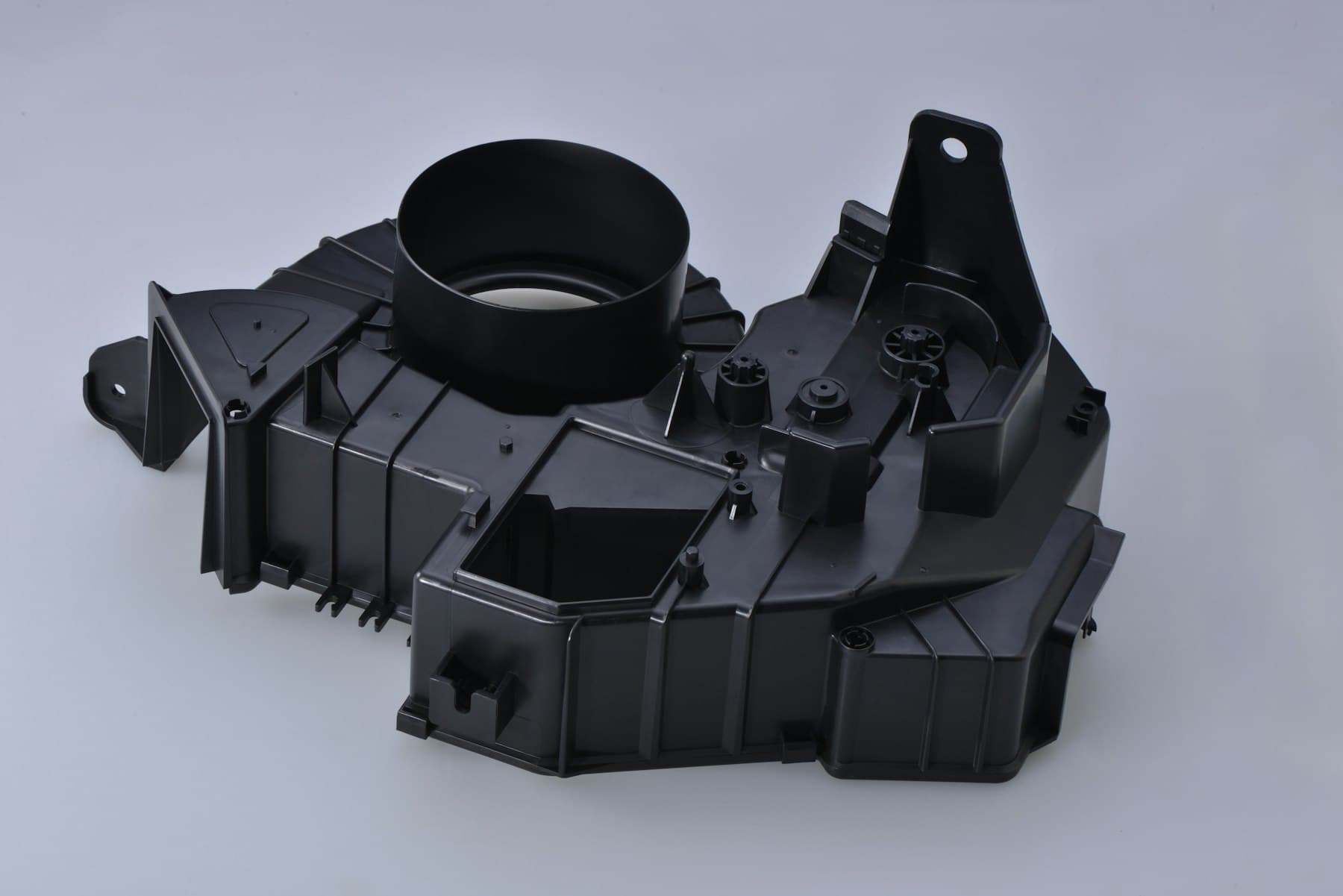
Give the supplier controlled CAD and a drawing that identify the interface like a critical dimension. Show primary datums, pull direction, no-gate and no-ejector zones, visible faces, permitted witness areas and the target boundary location. Include mating parts or a representative envelope when fit, compression or clearance matters.
02
Specify materials by exact grade and by the bond mechanism required
Injection molding material selection for a two-material component starts with the duty of each zone, then narrows to named grades. Record the resin producer, exact grade, colour or masterbatch direction, reinforcement or additive status, recycled-content direction if relevant, and the current technical data sheet to be used for review. Also state the desired hard/soft relationship, surface feel, stiffness, chemical exposure, temperature range and appearance priorities. A polymer-family name such as TPE, TPU, PP, ABS or PC is not a sufficient substitute for this record because grades, colourants, fillers and additives can alter processing, shrinkage, appearance and bonding behaviour.
Name the intended retention mode in the drawing notes or specification: chemical adhesion, mechanical interlock, geometric capture, or a defined combination. Chemical affinity can be useful, but it is grade-specific and must be confirmed rather than inferred from a generic resin pairing. BASF, for example, states that its Elastollan TPU can bond in multicomponent molding with compatible plastics but identifies polyolefin-based materials as incompatible with that material; that is useful evidence for a starting discussion, not approval of a different TPU grade or finished part. If mechanical retention is relied on, show the feature geometry and identify whether the product must resist peel, shear, pull-off, torsion, flexing or only handling.
Check both resin suppliers’ current processing and compatibility instructions, including purge, contamination, drying and temperature-history restrictions. Ask whether the pair can run in the proposed equipment without cross-contamination concerns and whether second-shot conditions could distort, stress or damage the first shot.
03
Turn the material boundary into an engineered interface
The interface needs its own geometry review. Keep local wall changes, abrupt thin edges and poorly supported first-shot features visible in the section view. The first shot must survive the pressure of the second injection and remain accurately located; otherwise flash, deformation, incomplete coverage or a wandering boundary may occur. Plastics Technology notes that a rotary arrangement needs both shutoff control and support for the first-shot part against second-shot cavity pressure. Ask for a marked cross-section showing the second-shot cavity, shutoffs, supports, vents, gates and the proposed ejection direction rather than accepting a process label alone.
Define the permitted appearance: whether a flash-free edge is essential, where a witness, gate vestige or knit line may occur, and whether a step is flush, proud or recessed. Give a visual comparator or written visual classes and define viewing conditions. Finish and colour can affect draft, texture, gate location and perceived boundary quality.
Dimensional requirements should reflect the two-material construction. Dimension a hard locating feature to its relevant hard-material datum where practical, and avoid applying an undifferentiated tight tolerance across a flexible overlay unless its function truly requires it. Shrinkage, cooling, geometry and tool design influence molded dimensions; the two materials can add another layer of movement and constraint. Identify which dimensions are critical to assembly, when they are measured, whether the part is conditioned before measurement, and whether a functional gauge or assembly trial is more meaningful than a broad array of cosmetic measurements.

04
Request the tool concept that matches the part and programme
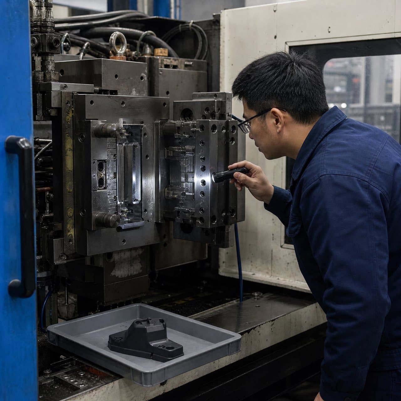
Ask suppliers to propose and explain the transfer method instead of prescribing an elaborate tool arrangement from an early render. Rotary mold tooling can move first-shot cores or parts into the second-shot position within a coordinated cycle, while movable-core arrangements change the cavity internally. A separate-tool transfer approach may also be considered where programme needs, automation and part geometry point elsewhere. These are different engineering choices, not interchangeable names. The molder should identify the assumed machine configuration, number of injection units, cavity count, transfer method, gating, runner arrangement, cooling concept, first-shot location method and any manual or automated handling assumption.
The comparison below is a buyer’s prompt for a concept review, not a rule for choosing a process. Cycle, capacity, tool investment, maintenance, part geometry and production volumes are programme-specific. Request the trade-off in writing and make any volume or ramp figures explicit rather than assuming a configuration is justified by a generic threshold.
| Concept to review | How the first shot reaches the second shot | Specification questions for the buyer | Typical risk to expose early |
|---|---|---|---|
| Rotary-platen two-shot tool | The tool or platen rotates the first-shot core or part into the second-shot station. | What machine interface, alignment control, cavity balance, supports and shutoffs are assumed? | Off-centre loading, misalignment, insufficient first-shot support or flash at the boundary. |
| Movable-core or core-back tool | A moving core changes the cavity after the first injection before the second material is injected. | Which core motion, locking and pressure-resistance assumptions are required, and where is the substrate supported? | Core movement, unsupported substrate areas or a narrow window for controlling the interface. |
| Separate-tool transfer or overmold route | A formed substrate is moved to a second mold or station for the second material. | How is the substrate located, kept clean, handled, inspected and protected from damage between operations? | Transfer variation, cooling-related adhesion change, handling marks or added traceability needs. |
05
Release against evidence, then control change
Write a part-level approval plan before tool release. It should link each claim to a practical check: dimensional fit to agreed datums or a functional gauge; appearance to a signed visual standard; coverage to defined zones; retention to a part-relevant test; and sealing, wear, chemical exposure or temperature cycling to a product-owner-defined method when those functions matter. State the sample condition, quantity logic, acceptance owner and disposition route for deviations. A peel result, for example, is only meaningful if its specimen geometry, loading direction, rate, conditioning and acceptance basis represent the intended use. Do not claim compliance or performance from an untested material pairing.
For multi material injection molding, keep the controlled CAD and drawing revision, resin grades, colour references, tool revision, sample identification, inspection record and exceptions together. Define what happens if the resin, colourant, regrind policy, tool, gate, cavity, machine arrangement or process window changes. Re-evaluation should match the risk: a hidden colour change may need less evidence than an interface change on a seal or load-bearing feature.
Use regional language carefully in purchasing documents. North American teams may use two shot molding, European teams may say 2K or two-component molding, and two color molding may describe a colour-focused construction rather than a functional material interface. Define the actual sequence and performance intent in the RFQ so terminology does not conceal different assumptions. Where the destination market or customer imposes documentation, chemical, environmental or product requirements, list the applicable requirement and verification owner rather than assuming that the molding process confers approval.
Practical takeaway
Before you move
to the next review.
- Map every hard and soft zone to its function, service exposures, visible faces, mating interfaces and retention loads.
- Freeze the proposed producer, exact resin grade, colour or additive direction, technical-data-sheet revision and permitted substitution rule for both materials.
- Mark the bond mechanism and provide cross-sections for all mechanical locks, shutoffs, first-shot supports, gates, vents and critical material boundaries.
- Request a written tool and transfer concept that names the machine assumptions, cavitation, location method, cooling, ejection and handling responsibilities.
- Agree part-specific samples, functional and visual checks, measurement conditions, acceptance owners and re-approval triggers before tool release.
FAQ
Common questions
Can we specify a TPE over a rigid plastic without naming exact grades?
That is usually too broad for release. TPE and the rigid resin each cover many grades with different additives, hardnesses, flow, colour response and adhesion behaviour. Name the intended grades or a controlled shortlist, state the required bond mechanism and service case, then ask the molder and material suppliers to verify the pairing for the proposed construction.
When is a mechanical interlock needed if the materials appear to bond?
It can be appropriate when the interface must resist peel, repeated flexing, moisture, thermal cycling, chemical exposure or loads that make chemical adhesion alone uncertain. The decision should follow the actual grade pair, interface geometry and product test plan. A mechanical feature is not automatically better; it also changes flow, shutoffs, tool complexity and potential stress concentrations.
What should an approval sample prove for a multi-material part?
It should prove the agreed part requirements, not merely show that both materials can be molded together. Depending on the part, that may include boundary location, coverage, appearance, fit to mating parts, relevant dimensional checks, retention or seal performance and the traceability of the grades and tool revision used. Define the method and acceptance decision before sampling.
References
Source material
- [1] Plastics Technology, Two-Shot Molding and Tool Design.
- [2] BASF, Processing Injection Moulding: Elastollan TPU.
- [3] Protolabs, Injection Molding Guide: Process, Design Tips and Materials.
- [4] SyBridge Technologies, What You Need To Know About Material Compatibility For Multi-Material Injection Molding.
This guide is general information for early procurement and engineering discussion. It does not replace product-specific DFM, qualification, validation, regulatory assessment or legal advice.